Data measuring and calculating method for uniaxial tensile test
A uniaxial tensile and data measurement technology, which is applied in the field of measurement and calculation of test data, and can solve problems such as grid size effect, grid size definition, failure strain setting, etc.
Inactive Publication Date: 2012-09-05
肖锋
View PDF1 Cites 0 Cited by
- Summary
- Abstract
- Description
- Claims
- Application Information
AI Technical Summary
Problems solved by technology
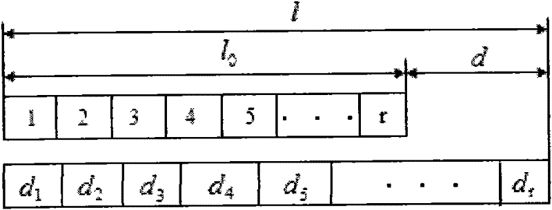
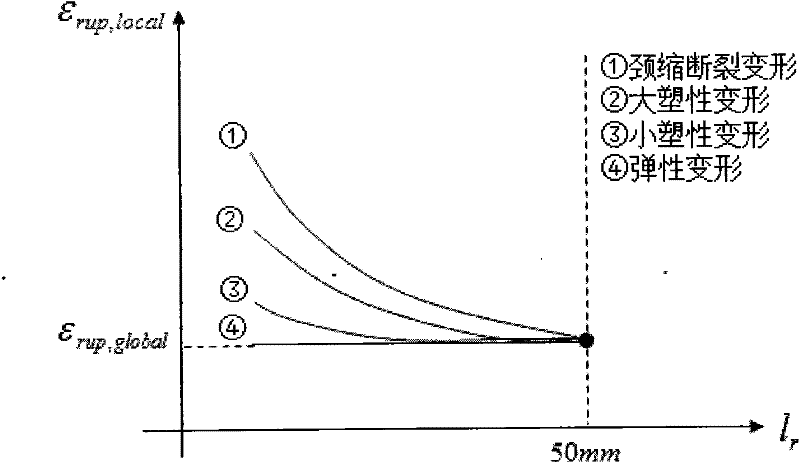
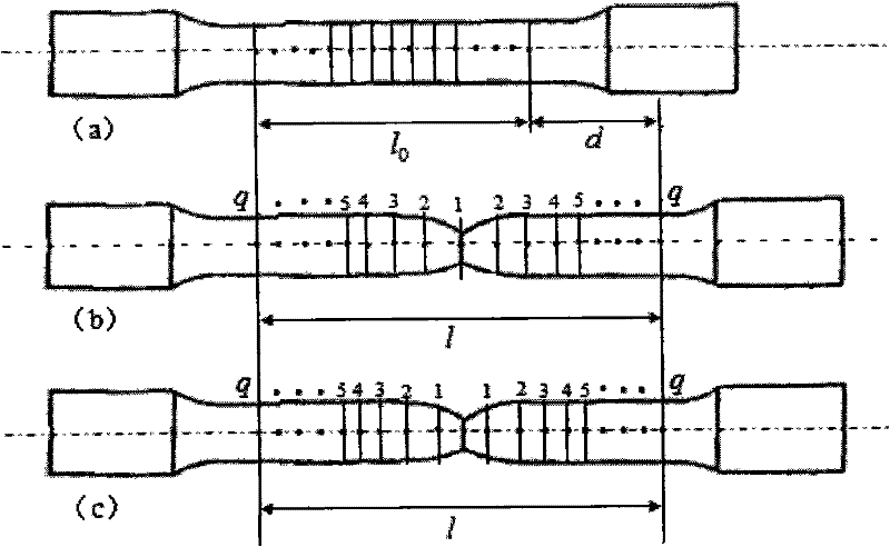
[0042] In view of the deficiencies in the prior art, the technical problem to be solved by the present invention is: many difficult problems existing in the finite element method, such as grid size effect, grid size definition of different deformation modes of the structure, failure in the material strain failure model Strain setting and other issues, providing theoretical explanations and solutions
Method used
View moreImage
Smart ImageViewing Examples
Examples
Embodiment 1
Embodiment 2
Embodiment 3
Login to View More PUM
 Abstract
The invention discloses a data measuring and calculating method for a uniaxial tensile test, which comprises the following steps of: marking a measuring point; measuring test data; calculating real breaking strain stress; and drawing an engineering and real stress strain curve. The method of the invention can obtain engineering and real stress strain curves in different reference lengths in the same uniaxial tensile test, establishes a corresponding relationship between the reference length effect and the mesh size effect and provides a thorough solution for the mesh size effect problem in a finite element method, i.e. a real stress strain curve in the equal reference lengths is defined for the same material with different mesh sizes. Meanwhile, theoretical explanation is provided for thepractical problems, such as mesh size effect, energy absorption, material strain invalidation, and the like according to a uniaxial tensile basic theory provided by the invention, therefore, the invention has important theory and engineering practical significance.
Description
technical field [0001] The invention relates to a test method for a uniaxial tensile test, in particular to the measurement and calculation of test data. Background technique [0002] In the vehicle crash simulation analysis, structural deformation includes material crushing deformation, bumper and anti-collision plate bending deformation, solder joint failure and other large material deformations. Reach the length required to describe the mesh deformation of the simulation model. Therefore, when the stress-strain exceeds a given curve, the software processing generally extends the stress-strain relationship along the tangent automatically, or artificially extends the curve when inputting the curve. In addition , from the perspective of engineering analysis, the strain failure criterion is the most promising material failure model for engineering applications. It has only one failure parameter and can be obtained from uniaxial tensile tests. [0003] Generally speaking, the...
Claims
Login to View More Application Information
Patent Timeline
 Patent Type & Authority Patents(China)
IPC IPC(8): G01N3/08
Inventor 肖锋
Owner 肖锋
Features
- R&D
- Intellectual Property
- Life Sciences
- Materials
- Tech Scout
- Unparalleled Data Quality
- Higher Quality Content
- 60% Fewer Hallucinations
Learn More Browse by: Latest US Patents, China's latest patents, Technical Efficacy Thesaurus, Application Domain, Technology Topic, Popular Technical Reports.
© 2025 PatSnap. All rights reserved.Legal|Privacy policy|Modern Slavery Act Transparency Statement|Sitemap|About US| Contact US: help@patsnap.com


