Optimization design method for air conditioner airduct structure

An optimized design and air conditioner technology, which is applied in the direction of instruments, calculations, and special data processing applications, can solve the problems of shortened test time, long test cycle, and high production cost, so as to shorten the development cycle, improve R&D efficiency, and save production costs. Effect

Active Publication Date: 2011-02-16
HISENSE (SHANDONG) AIR CONDITIONING CO LTD
View PDF4 Cites 26 Cited by
  • Summary
  • Abstract
  • Description
  • Claims
  • Application Information

AI Technical Summary

Problems solved by technology

[0004] In order to solve the problems of high production cost and long test period of the existing air-conditioner air duct structure design method, the present invention provides an optimal design method for the air-conditioner air duct structure, which reduces the cost and shortens the test time

Method used


Image

  • Optimization design method for air conditioner airduct structure
  • Optimization design method for air conditioner airduct structure
  • Optimization design method for air conditioner airduct structure

Examples


Embodiment 1

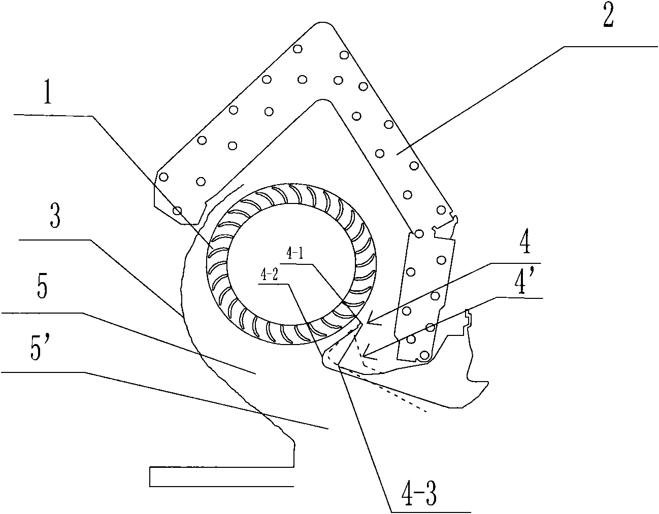
[0026] Embodiment one, see figure 1 As shown, for this embodiment, two air conditioner air duct models with different structures are first established by using PROE software, and the operating platform of the PROE software is a computer. In this embodiment, the air conditioner air duct model can specifically include four parts: evaporator, air duct, volute and volute tongue; wherein the air conditioner air duct model includes fan 1, evaporator 2, volute 3, and volute tongue 4, and the air duct 5 surrounded by the fan 1, the evaporator 2, the volute 3 and the volute tongue 4, for the convenience of describing the two air duct structures, this embodiment defines three characteristic points of the vortex tongue 4: the vortex tongue 4 Extending to the highest point 4-1 of the evaporator 2 part, the closest point 4-2 of the volute tongue 4 to the volute 3, and the farthest point 4-3 of the vortex tongue 4 to the fan 1. figure 1 Also includes air conditioner air duct model 2, inclu...

Embodiment 2

[0047] Embodiment two, see Figure 4 As shown, let the vortex tongue gap h be the distance between the fan 1 and the vortex tongue 4 . The difference between this embodiment and the first embodiment is that the structure of the volute tongue 4 is not changed, and the optimal design of the air duct structure of the air conditioner is realized by optimizing and improving the value of the volute tongue gap h.

[0048] First, use PROE software to establish two different air conditioner air duct models, which are respectively recorded as model 3 and model 4. The vortex tongue clearance h of the two air conditioner air duct models are 3mm and 4mm respectively. The import of generated files, the setting of model parameters and variable parameters, and the setting of other parameters are consistent with the operation method described in Embodiment 1, and will not be repeated here.

[0049] The noise of the two air conditioner air duct models and the air volume blown out of the outlet...


PUM


Abstract

The invention discloses an optimization design method for an air conditioner airduct structure, comprising the following steps of: (1) establishing at least two airduct models; (2) respectively carrying out grid partition on the spanned files of the airduct models, and importing generated grid files into CFD (Computational Fluid Dynamics) software; (3) setting model parameters and variable parameters in the CFD software; (4) working out noise and air quantity after the CFD software simulate air flow reaches the quasi-stable state; (5) comparing to obtain models with big air quantity and small noise in the airduct models, taking the models as the preselected scheme, then carrying out the airduct model modification on the preselected scheme for at least one time, and returning to the step (2) to determine a final airduct model; and (6) producing an air conditioner model machine by combining with the final airduct model, and conducting a noise experiment and an air quantity experiment. By using the optimization design method for the air conditioner airduct structure, the design cost of the air conditioner airduct structure can be reduced, the parameter test time is shortened and the use becomes convenient.

Description

technical field [0001] The invention belongs to the technical field of air conditioner structural optimization design methods, and in particular relates to an optimal design method for the air duct structure of an air conditioner. Background technique [0002] In the existing air conditioner air duct structure design, technicians generally manufacture various air conditioner prototypes with different air duct structures based on existing experience, and then conduct noise experiments and air volume experiments to measure the air duct that can reflect Advantages and disadvantages of performance parameters: air conditioner noise and the air volume blown by the air duct of the air conditioner per unit time, and then according to the measurement results, the air duct structure of the air conditioner with a large air volume blown out per unit time and low noise is compared as the final air duct The design method is used for the production of finished air conditioners. Using this...

Claims


Application Information

Patent Timeline
Patent Type & Authority Applications(China)
IPC IPC(8): G06F17/50
Inventor 杨娟赵可可徐超
Owner HISENSE (SHANDONG) AIR CONDITIONING CO LTD
Why Eureka
Try Eureka