Calibration system and method for cd-rom light-emitting device

A technology for a light-emitting device and a calibration system, which is applied to recording/reproducing by an optical method, a method for comparing with a reference electrical parameter, a measuring device, etc., can solve problems such as increasing costs, and achieve the effect of reducing manufacturing costs.

Inactive Publication Date: 2011-02-16
MEDIATEK INC
View PDF2 Cites 0 Cited by
  • Summary
  • Abstract
  • Description
  • Claims
  • Application Information

AI Technical Summary

Problems solved by technology

In this way, the cost of manufacturing will be greatly increased

Method used


Image

  • Calibration system and method for cd-rom light-emitting device
  • Calibration system and method for cd-rom light-emitting device
  • Calibration system and method for cd-rom light-emitting device

Examples


Embodiment Construction

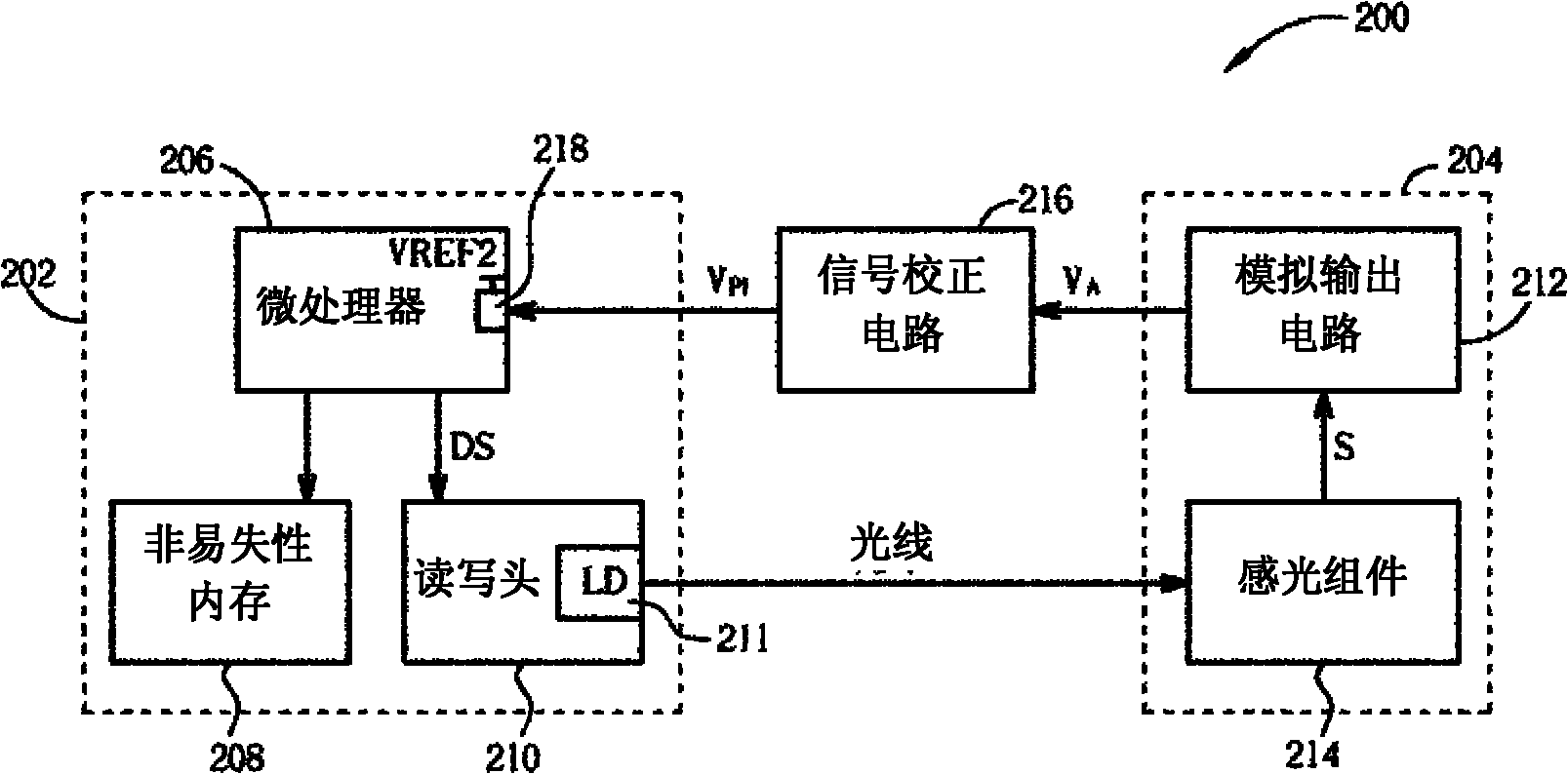
[0037] figure 2 Shown is a block diagram of a power calibration system 200 according to the first embodiment of the present invention. The power calibration system 200 includes a device under test 202 ; a power meter 204 electrically connected to the device under test 202 and used as a light sensor; and a signal calibration circuit 216 . In this embodiment, the device under test 202 includes a microprocessor 206 , a non-volatile memory 208 , and a read / write head 210 . Wherein, the read / write head 210 is used to control a light emitting device (light emitting device, such as figure 2 A laser diode 211 is shown). In practice, the microprocessor 206 can be a central processing unit (CPU) in the device under test 202, and the non-volatile memory 208 can be realized by an electrically erasable programmable read-only memory (EEPROM). In this example, the power measuring device 204 includes a photo sensor 214 and an analog output circuit 212 .

[0038]The operation of calibrat...


PUM


Abstract

The invention provides a calibration system and a method for a CD-ROM light-emitting device. The calibration system for a light-emitting device comprises a diode laser as a device to be calibrated, a first microprocessor, an optical detector and a signal calibration circuit. In a calibration mode, the first microprocessor controls power of the light-emitting device by changing values of a drive signal to the light-emitting device, receives a power indication corresponding to the light emitted by the light-emitting device, and determines a power relationship relating values of the drive signal to powers of the light-emitting device according to a power indication for each of a plurality of values of the drive signal. The light detector is used for detecting the light emitted by the light-emitting device to generate an analog signal having a direct ratio to the strength o the output light. The signal calibration circuit having a set reference voltage is used for generating a power indication reverse to the analog signal so as to guide the power indication to be a set maximum value when the analog signal shows that no light is output from the light-emitting device, wherein the set maximum value is a function of the set reference voltage.

Description

[0001] This application is a divisional application with the application number 200510108089.4, the application date is September 29, 2005, and the invention name is "light emitting device calibration system and related method". technical field [0002] The present invention relates to a light emitting device calibration system and a related method, in particular to a light emitting device calibration system and a related method for an optical drive. Background technique [0003] As the market demand for high-capacity storage media continues to grow, the role played by compact discs (CDs) becomes more important. In the process of recording data, the optical read-write unit (OPU) of the optical drive emits light beams on the dye layer of the disc to burn pits, so as to record data on the disc. When the beam is stopped, the dye layer changes up to form so-called lands. The reflection ability of the pothole area is worse than that of the flat area, so the pothole area and the ...

Claims


Application Information

Patent Timeline
Patent Type & Authority Applications(China)
IPC IPC(8): G11B7/13
CPCG01J1/32G01J2001/4247
Inventor 詹昆益孙上斌
Owner MEDIATEK INC
Why Eureka
Try Eureka