Coal machine middle groove cantilever welding equipment

A welding equipment, coal machine technology, applied in the direction of welding equipment, welding equipment, auxiliary welding equipment, etc., can solve the problems of small increase in production efficiency, irregular shape, large cost investment, etc., to achieve the elimination of weld undercut, welding Beautiful seam formation and improved welding efficiency

Active Publication Date: 2013-04-10
AOTAI ELECTRIC
View PDF7 Cites 0 Cited by
  • Summary
  • Abstract
  • Description
  • Claims
  • Application Information

AI Technical Summary

Problems solved by technology

[0004] The welding trolley with track, the welding torch is installed on the side of the trolley pointing to the welding seam position, the track is laid flat on the middle plate or bottom plate of the middle feeding chute during welding, the trolley is placed on the track and walks along the track, because the trolley itself takes up space , so the welding torch cannot weld the weld seam at the end of the feeding chute in the middle;
[0005] 2. High cost investment and complex operation
[0006] The welding robot is fixed on one side of the welding platform of the middle feeding chute, and can weld each welding position of the middle feeding chute, but the cost investment is large and the production efficiency is not greatly improved; the middle feeding chute is a casting with irregular shape and difficult to locate. When welding, each workpiece needs to be taught before welding, the operation is more complicated, and the quality requirements of welding workers are higher, so it is not easy to popularize in small and medium-sized enterprises;

Method used


Image

  • Coal machine middle groove cantilever welding equipment
  • Coal machine middle groove cantilever welding equipment
  • Coal machine middle groove cantilever welding equipment

Examples


Embodiment Construction

[0035] The present invention will be further described below in conjunction with the accompanying drawings and embodiments.

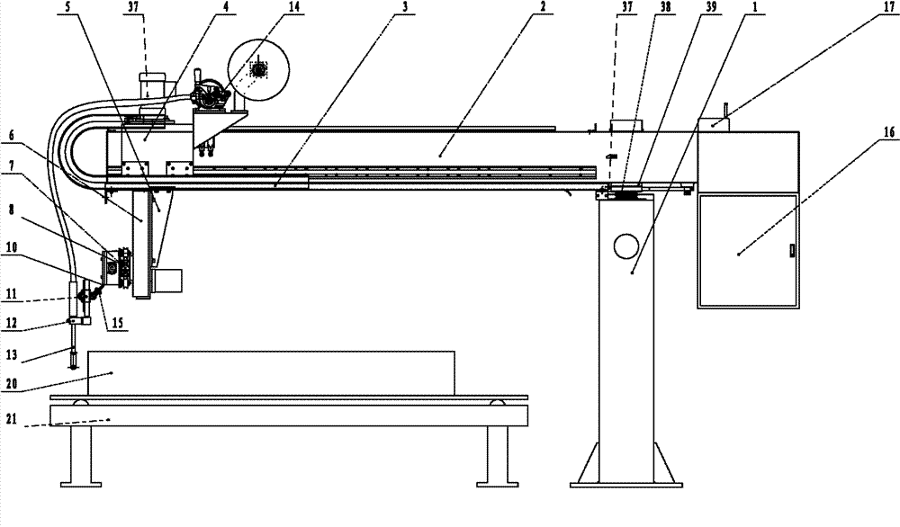
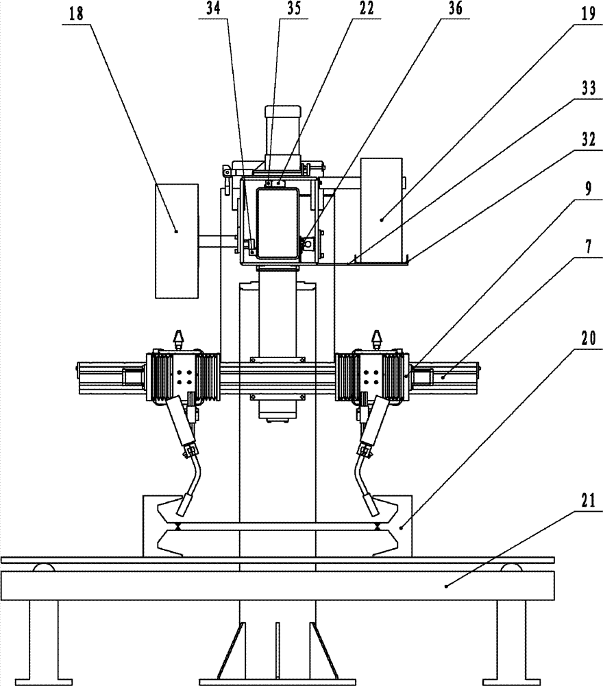
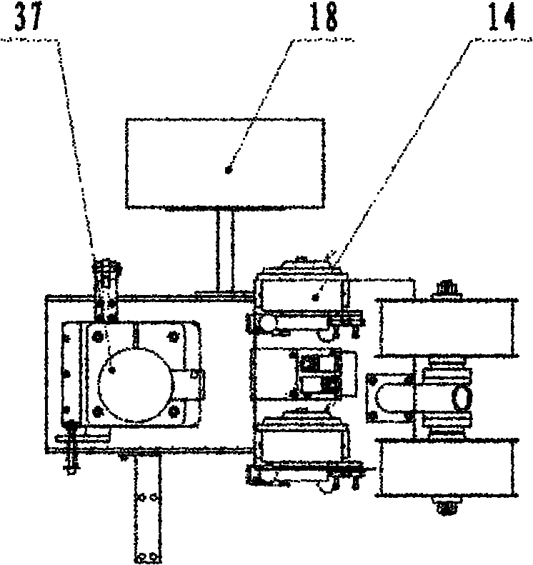
[0036] figure 1 , figure 2 , image 3 , Figure 4 Among them, it includes a vertical beam mechanism 1, a beam mechanism 2, a sliding box mechanism 4, an electric carriage mechanism 6, a welding torch swing device 9, a wire feeding mechanism 14 and an electric control system 16; wherein the beam mechanism 2 is connected to the The vertical beam mechanism 1 is connected and can rotate around the vertical beam mechanism 1 within the range of ±90°, and the angle positioning is carried out by the locking mechanism; an electric control system 16 is provided at the end of the beam mechanism 2, and a slide for relative movement is provided at the other end. The box mechanism 4 and the wire feeding mechanism 14 are equipped with an electric carriage mechanism 6 at the bottom of the sliding box mechanism 4, and a welding gun swing device 9 is installed on the...


PUM


Abstract

The invention relates to novel coal machine middle groove cantilever welding equipment, comprising a vertical beam mechanism, a transverse beam mechanism, a sliding box mechanism, an electric carriage mechanism, a welding gun swinging device, a wire feeder and an electronic control system; wherein the transverse beam mechanism is connected with the vertical beam mechanism by a spindle and can rotate around the vertical beam mechanism in the range of minus or plus 90 degrees; the terminal of the transverse beam mechanism is provided with the electric control system, the other end is provided with the sliding box mechanism and wire feeder which move relatively, the wire feeder is arranged at the top of the sliding box mechanism, the lower part of the sliding box mechanism is provided with the electric carriage mechanism, the electric carriage mechanism is provided with the welding gun swinging device, and a welding gun is connected with the welding gun swinging device. The invention hasthe advantages that structure is compact and operation is convenient, and the invention aims at improving automation and mechanization level of middle charging groove 'K' and 'V' welding line welding, improving production efficiency, improving welding product and reducing labour intensity of welder, so as to satisfy the requirement that quantity demand and quality of middle charging groove welding are continuously increased.

Description

technical field [0001] The invention relates to an automatic welding equipment for "K" and "V" groove welding, in particular to a new type of cantilever welding equipment for the middle groove of a coal machine for straight seam welding. Background technique [0002] The middle feeding chute is the main part of the scraper conveyor system, and its welding quality directly determines the life and mining volume of the entire coal mining system. Moreover, the amount of welding required for the middle feeding chute accounts for more than 80% of the entire scraper conveyor system, so improving the welding quality and welding efficiency of the middle feeding chute has always been highly valued by manufacturers and users. At present, manual gas shielded welding is mostly used for the welding of the middle feeding trough. Although it can basically meet the welding production requirements, it is difficult to operate, the welding quality is greatly affected by human factors, poor appl...

Claims


Application Information

Patent Timeline
Patent Type & Authority Patents(China)
IPC IPC(8): B23K37/00B23K37/02B23K9/12B23K9/32
Inventor 张光先刘增晓高勇辉赵中林
Owner AOTAI ELECTRIC
Why Eureka
Try Eureka