
Automobile brake pedal mechanism and pedal feel simulator thereof

A simulator and pedal technology, applied to the field of online control brake pedal mechanism and its components, can solve the problems of difficult transplantation, unsatisfactory pedal brake feeling, and inability to adjust the brake pedal mechanism, so as to achieve easy operation, good feeling, and improved braking The effect of dynamic stability

Active Publication Date: 2012-07-25
南通特力锻压机床有限公司 +1
View PDF1 Cites 24 Cited by
  • Summary
  • Abstract
  • Description
  • Claims
  • Application Information

AI Technical Summary

Problems solved by technology

[0007] The technical problem to be solved by the present invention is that the existing brake pedal mechanism cannot be adjusted according to the actual situation of the vehicle and the driver, it is difficult to transplant on different models, and the braking feeling of the pedal is not ideal. pedal feeling simulator, and further proposed a brake pedal mechanism including the pedal feeling simulator, the mechanism in the case of cooperating with other devices, according to the speed of pedal movement or microwave range radar provided by the front vehicle, personnel or The distance information of the obstacle adjusts the damping of the pedal feel simulator, so that the driver has a good handling feeling, thereby improving braking stability, comfort and response speed

Method used


Image

  • Automobile brake pedal mechanism and pedal feel simulator thereof
  • Automobile brake pedal mechanism and pedal feel simulator thereof
  • Automobile brake pedal mechanism and pedal feel simulator thereof

Examples


Embodiment 1

[0037] (Embodiment 1, pedal feeling simulator)

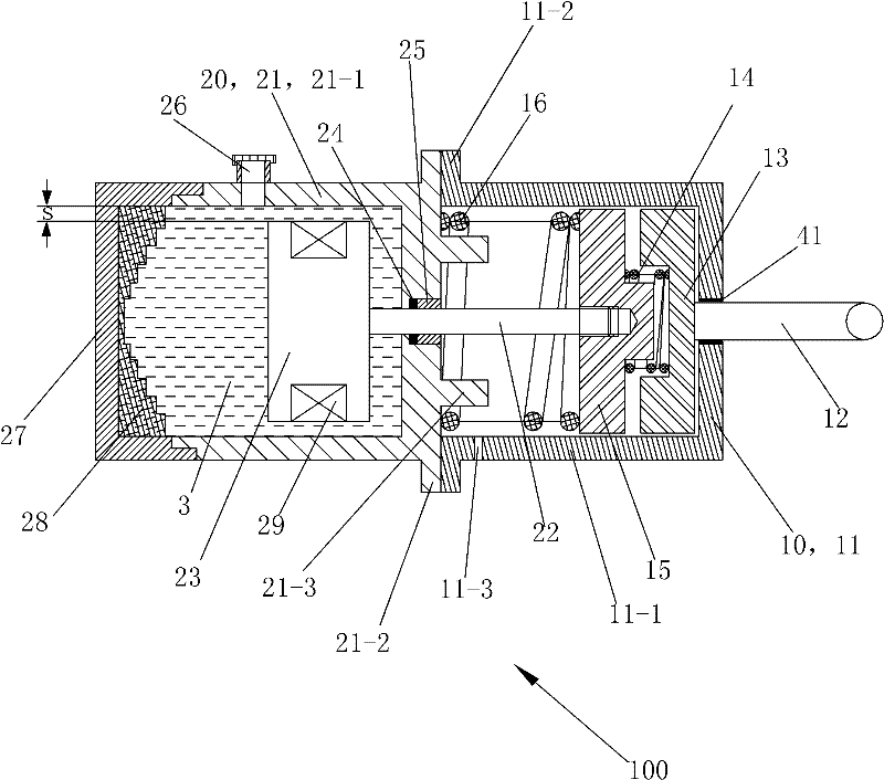
[0038] See figure 1 , the pedal feel simulator 100 of this embodiment includes a front cylinder assembly 10 , a rear cylinder assembly 20 and a magneto-rheological fluid 3 .

[0039] Front cylinder assembly 10 comprises front cylinder 11, front piston rod 12, first piston 13, free stroke spring 14, second piston 15 and return spring 16, first piston 13 and second piston 15 and front cylinder 11 Swipe back and forth to connect.

[0040] The front cylinder body 11 is an integral piece made of steel, including a front cylinder main body 11-1 and a second flange connecting portion 11-2 connected to the outer periphery of the rear end side of the front cylinder main body 11-1. The front cylinder main body 11-1 is a cylinder with a front end plate, the rear end of the front cylinder main body 11-1 is open, and the center of the front end plate of the front cylinder main body 11-1 has a central hole coaxial with the cylinder , The ...

Embodiment 2

[0057] (Embodiment 2, brake pedal mechanism of automobile)

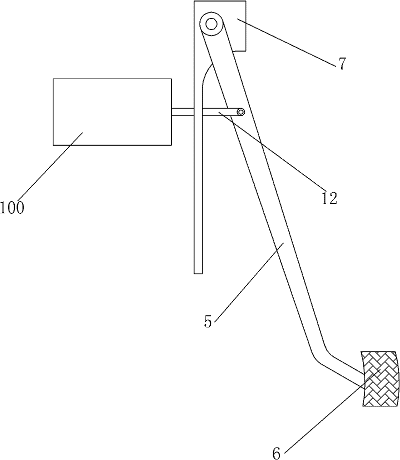
[0058] See figure 2 The brake pedal mechanism of the present embodiment automobile comprises a pedal feeling simulator 100, a pedal displacement sensor 41, a wheel speed sensor 42, a microwave ranging radar 43, a pedal arm 5, a pedal 6, a support 7, and a low voltage direct current control power supply 8.

[0059] The low-voltage DC control power supply 8 includes a central processing unit 80 , a low-voltage power supply 81 , a voltage regulation control circuit 82 , a voltage feedback circuit 83 , a current limiting circuit 84 , an IGBT drive chopper circuit 85 and a power filter circuit 86 .

[0060] The central processing unit 80 is provided with a pedal displacement signal input end, a wheel speed signal input end, a microwave ranging signal input end, a pulse width modulation signal output end and a voltage regulation signal output end. The signal output end of the pedal displacement sensor 41 is electrically ...


PUM


Abstract

The invention relates to an automobile brake pedal mechanism and a pedal feel simulator thereof. The brake pedal mechanism comprises a brake pedal, a pedal displacement sensor, the pedal feel simulator, a microwave distance-measuring radar, a central processing unit and the like, wherein the pedal displacement sensor adopts two variable resistors for identifying the brake intention of a driver; the pedal feel simulator is based on a magnetorheological fluid principle; the central processing unit can controls the voltage volume of a coil and adjusts the damp of the simulator according to the pedal speed or distance information of front vehicles, people or barriers provided by the microwave distance-measuring radar, so that the driver has excellent operation feel, and the stability, comfortand safety of brake can be improved. Meanwhile, by changing the set value in the central processing unit, the damp output curve of the pedal feel simulator can be adjusted to meet requirements of different vehicle models or drivers. The automobile brake pedal mechanism and the pedal feel simulator thereof have the advantages of simple structure, quick response, good adaptability and the like, andis convenient in operation,.

Description

technical field [0001] The invention relates to the field of automobile brakes, in particular to a brake-by-wire brake pedal mechanism and its components for automobiles. Background technique [0002] Automobile braking mechanism is an important device to ensure the safe driving of automobiles. The working principle of the brake system commonly used at present is: the driver steps on the brake pedal, and the brake pedal moves the piston of the master cylinder through the push rod, so that the oil in the brake master cylinder flows into the cylinder under a certain pressure. Wheel cylinders, the corresponding pressure is formed in the wheel cylinders and acts on the brake discs (drums) to implement vehicle braking. For the traditional braking system, the brake master cylinder and the wheel cylinder need to be connected through a long liquid or gas transmission pipeline, there are many valve components, and the braking response speed is slow. The addition of electronic contr...

Claims


Application Information

Patent Timeline
Patent Type & Authority Patents(China)
IPC IPC(8): B60T7/06
Inventor 王奎洋唐金花贝绍轶
Owner 南通特力锻压机床有限公司
Learn More