
Short-flow high-efficiency spinning machine used for producing multicomponent yarn

A short process and spinning machine technology, applied in the field of textile processing, can solve the problems of frequent doffing tube changes, affecting the appearance of fabrics, and increasing the number of yarn joints

Inactive Publication Date: 2011-03-09
WUHAN TEXTILE UNIV +2
View PDF6 Cites 12 Cited by
  • Summary
  • Abstract
  • Description
  • Claims
  • Application Information

AI Technical Summary

Problems solved by technology

The small package of the spun bobbin results in frequent doffing and changing bobbins, high labor intensity, and a large turnover of spun yarn required; at the same time, due to the high spinning tension, it will also affect the steel ring and steel wire on the spinning frame. Rings and other machine parts produce very serious wear and tear
At the same time, frequent tube changes will also increase the number of joints in the final yarn, which will also affect the appearance of the fabric
[0004] The ratio of the opening width of the two arms of the flyer on the twisting and winding mechanism of the traditional suspended-spindle roving frame to the arm length of the flyer is usually 2:5. This size structure of the flyer makes the roving on the roving bobbin The maximum winding diameter is about φ150mm, and the maximum yarn capacity is about 2.5kg. The spun roving is used for further processing in the spinning process of the worsted processing system, and the process is relatively cumbersome.

Method used

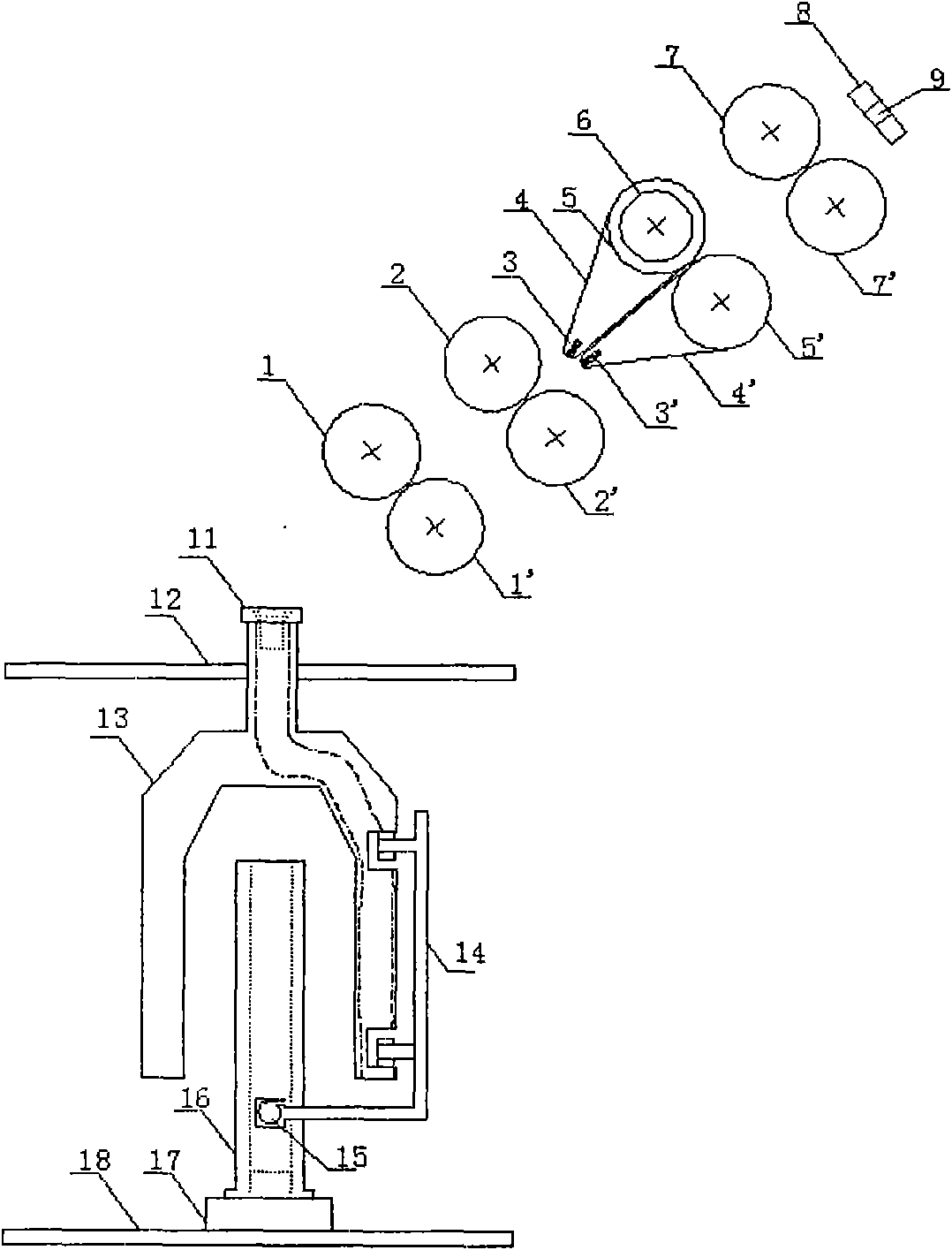
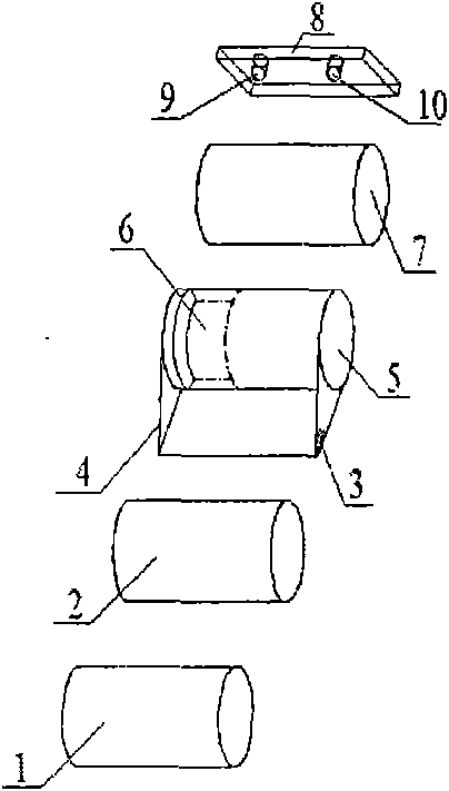
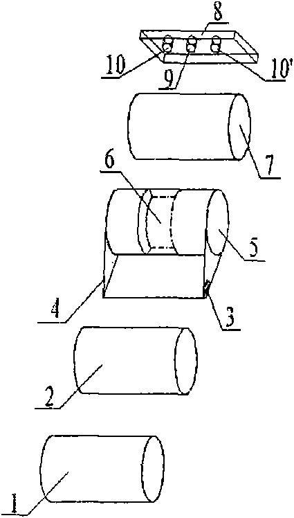

Image

  • Short-flow high-efficiency spinning machine used for producing multicomponent yarn
  • Short-flow high-efficiency spinning machine used for producing multicomponent yarn
  • Short-flow high-efficiency spinning machine used for producing multicomponent yarn

Examples


Embodiment 1

[0032] See figure 2 In the middle of one side of the third top roller 5 of the spinning machine, a positioning annular groove 6 with a width of 12 mm and a depth of 3 mm is opened, and a positioning yarn feeding hole 9 with a diameter of 10 mm and a positioning yarn feeding hole 9 with a diameter of 10 mm are opened on the positioning yarn feeding device 8. Aperture is the yarn feeding hole 10 of 10mm, and positioning yarn feeding hole 9 and yarn feeding hole 10 are on the same horizontal line. The axis of the positioning yarn feeding hole 9 is collinear with the center line of the positioning annular groove 6, and the yarn feeding hole 10 is positioned at the side of the positioning yarn feeding hole 9. Setting the center distance of the second roller 2' and the back roller 7' is 102mm, and setting the second roller 2' and the third roller 5' center distance is 45mm. Fix the flyer 13 on the upper dragon shaft 12 through the bearing, install a plurality of grooved annular fa...

Embodiment 2

[0037] See image 3 In the middle part of the third top roller 5 of the spinning machine, a width of 10 mm and a depth of 3.5 mm are opened to position the annular groove 6. On the positioning yarn feeding device 8, a positioning yarn feeding hole 9 and a yarn feeding hole 10 and a feeding hole 10 are opened. The yarn hole 10' is positioned on the same horizontal line as the yarn feeding hole 9, the yarn feeding hole 10 and the yarn feeding hole 10', and their apertures are 10mm. The axis of the positioning yarn feeding hole 9 is collinear with the center line of the positioning annular groove 6, and the yarn feeding hole 10 and the yarn feeding hole 10' are positioned at both sides of the positioning yarn feeding hole 9 respectively. Setting the center distance of the second roller 2' and the back roller 7' is 115mm, and setting the second roller 2' and the third roller 5' center distance is 55mm. Fix the flyer 13 on the upper shaft 12 through the bearing, install the inner ...

Embodiment 3

[0041] See Figure 4 On both sides of the third top roller 5 of the spinning machine, a positioning annular groove 6 and a positioning annular groove 6' with a width of 8 mm and a depth of 4 mm are opened respectively, and two positioning yarn feeding devices are provided on the positioning yarn feeding device 8. Hole 9 and 9 ' and a yarn feeding hole 10, positioning yarn feeding hole 9 and 9 ' and yarn feeding hole 10 are on the same horizontal line, and their apertures are 10mm. The axis of positioning yarn feeding hole 9 and positioning yarn feeding hole 9' is collinear with the midline of positioning annular groove 6 and 6' respectively, and yarn feeding hole 10 is positioned in the middle of positioning yarn feeding hole 9 and positioning yarn feeding hole 9'. Setting the center distance of the second roller 2' and the back roller 7' is 114mm, and setting the second roller 2' and the third roller 5' center distance is 40mm. Fix the flyer 13 on the upper shaft 12 through ...


PUM

PropertyMeasurementUnit
diameteraaaaaaaaaa
lengthaaaaaaaaaa

Abstract

The invention relates to a short-flow high-efficiency spinning machine used for producing the multicomponent yarn, belonging to the technical field of textile processing. The technical scheme of the invention is as follows: a single positioning ring groove or double positioning ring grooves are formed in different places of the surface of the third leather roller of the drawing mechanism of the spinning machine along the circumferential direction to ensure that a double apron drawing region and an apron drawing region are separately formed in the drawing mechanism and the demand that a plurality of fibers with different components and different lenghts are fed and drawn at the same time can be satisfied. After the drawn sliver is twisted, a wide-opening flyer is used for winding so as to form a large-size cone yarn package. The strength of the spun yarn meets the demand of the knitting machine or the spinning machine.

Description

technical field [0001] The invention relates to a short-flow high-efficiency spinning machine for producing multi-component yarns. The yarns spun by the spinning machine can be directly used for fabric weaving on shuttle looms and knitting machines, and belong to the technical field of textile processing. Background technique [0002] In recent years, blended products composed of multi-component raw materials have become very popular in the international market. The mixing of different raw materials (such as two-in-one, three-in-one) has expanded the use of textile materials and increased the style of such products. However, due to the large differences in the fineness, length and initial modulus of different raw materials, the difference in raw material performance will cause the problem of increased production difficulty when raw materials are mixed and woolen carding. For example, the rigidity of wool is relatively high, while the rigidity of viscose yarn and cashmere is ...

Claims


Application Information

Patent Timeline
Patent Type & Authority Applications(China)
IPC IPC(8): D01H5/70D01H5/78D01H5/86D01H5/72D01H7/26
Inventor 徐卫林田野沈小林杨进陈军华永诚甄雅璋
Owner WUHAN TEXTILE UNIV
Learn More