Rotor current control method of double-fed wind driven generator under power grid faults

A wind turbine and rotor current technology, applied in the direction of motor generator control, electronic commutation motor control, control generator, etc., can solve the problems of transient impact of protection circuit system, deterioration of power grid, increase of system cost, etc., to achieve suppression The effect of rotor overcurrent, rotor current suppression, and stable control

Inactive Publication Date: 2011-03-16
TIANJIN UNIV
View PDF3 Cites 25 Cited by
  • Summary
  • Abstract
  • Description
  • Claims
  • Application Information

AI Technical Summary

Problems solved by technology

This method protects the excitation converter and the rotor winding when the power grid fails, but at this time the generator runs in the induction motor mode and needs to absorb a large amount of reactive power from the power grid, which will further deteriorate the power grid; second, the protection circuit The switching operation will have a transient impact on the system; in addition, adding a new protection device increases the system cost
Some scholars have introduced a new topology structure. The control of this scheme is complex, and because the scheme operates off-grid when the power transmission system fails, it does not actively support the restoration of normal operation of the power grid; similarly, this scheme needs to increase the cost of the system

Method used


Image

  • Rotor current control method of double-fed wind driven generator under power grid faults
  • Rotor current control method of double-fed wind driven generator under power grid faults
  • Rotor current control method of double-fed wind driven generator under power grid faults

Examples


Embodiment Construction

[0025] The present invention will be further described below in conjunction with the accompanying drawings and embodiments.

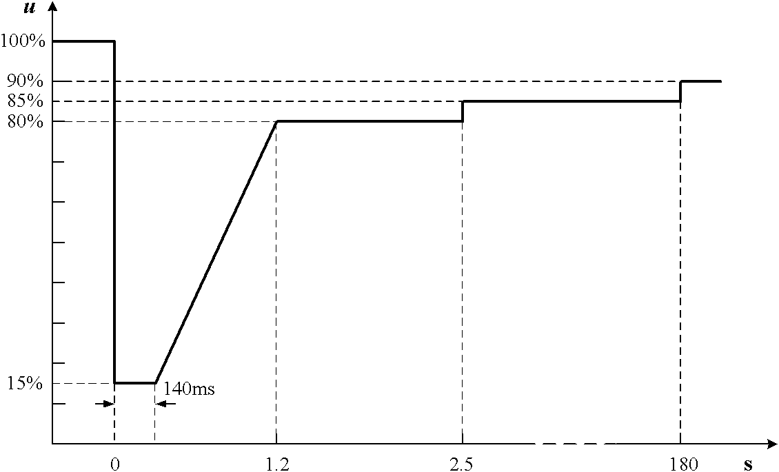
[0026] Power grid faults are generally divided into symmetrical faults and asymmetrical faults. Symmetrical faults are generally caused by three-phase-to-ground short-circuits in the grid. Asymmetrical faults are divided into single-phase-to-ground short-circuit faults, two-phase-to-ground short-circuit faults, and phase-to-phase short-circuit faults. The grid failure will cause the generator stator voltage to drop, and the change of the stator voltage will cause the generator stator flux linkage to change. Under normal circumstances, the generator stator voltage equation can be expressed as a space vector form:

[0027] u s = R s i s + dψ s dt - - - ...


PUM


Abstract

The invention belongs to the field of controlling a power conversion device of a wind driven generator, relating to a rotor current control method of a double-fed wind driven generator under power grid faults. The method comprises the following steps: obtaining the stator voltage and the rotor current under a two-phase static coordinates by utilizing the detected three-phase stator voltage and the three-phase rotor current through a 3/2 conversion module; calculating the stator magnetic flux linkage and the position angle; calculating the slip frequency angle and the slip frequency angular velocity; summating the stator magnetic flux linkage position angle and the rotor position angle, and then carrying out differentiation to obtain the sum of the magnetic flux linkage angular velocity and the rotor angular velocity; calculating the rotor current set values under the two-phase static coordinates of a rotor; respectively subtracting the rotor current set values under the two-phase static coordinates of the rotor with the rotor current under the two-phase static coordinates and obtaining the reference value of the rotor voltage under the two-phase static coordinates through the calculation by utilizing a performance requirement (PR) controller; and generating the switching signal of a control power device. The rotor current control method has the advantages that the rotor current oscillation of a double-fed induction generator (DFIG) resulted from power grid faults can be effectively inhibited, the grid in-service operation of the double-fed wind driven generator, and the operation performance of the DFIG under the power grid faults is enhanced.

Description

technical field [0001] The invention relates to a control method for a rotor-side inverter of a doubly-fed wind power generator (DFIG) under a grid failure, and belongs to the field of wind power generator control. Background technique [0002] Since the stator side of the doubly-fed induction generator (DFIG) is directly connected to the grid, it is very sensitive to grid faults. Power grid faults will cause sudden changes in the stator voltage of the generator, and the stator current will oscillate. At the same time, the active and reactive power and electromagnetic torque of the generator stator will also oscillate. In addition, due to the strong coupling between the rotor and the stator, the abrupt stator voltage will cause large fluctuations in the rotor current, which will affect the operating state of the doubly-fed machine. When the grid failure reaches a certain level, in order to protect the safe operation of the frequency conversion device, the wind turbine will ...

Claims


Application Information

Patent Timeline
Patent Type & Authority Applications(China)
IPC IPC(8): H02P9/14H02P21/08H02J3/38H02J3/18H02P21/22
CPCY02E40/30
Inventor 夏长亮王萌史婷娜陈炜
Owner TIANJIN UNIV
Why Eureka
Try Eureka