Numerical control cutting machine

A technology of cutting machine and stepping motor, which is applied in metal processing and other directions, can solve the problems of low working efficiency, insufficient safety performance and high labor intensity of cutting machine, and achieve the goal of improving production efficiency, obvious energy saving and high degree of automation Effect

Inactive Publication Date: 2011-03-23
陆存林
View PDF6 Cites 27 Cited by
  • Summary
  • Abstract
  • Description
  • Claims
  • Application Information

AI Technical Summary

Problems solved by technology

[0003] The purpose of the present invention is to provide a numerical control cutting machine, which overcomes the problems of low working efficiency, slow speed, high labor intensity and insufficient safety performance of the traditional blanking machine

Method used


Image

  • Numerical control cutting machine
  • Numerical control cutting machine

Examples


Embodiment Construction

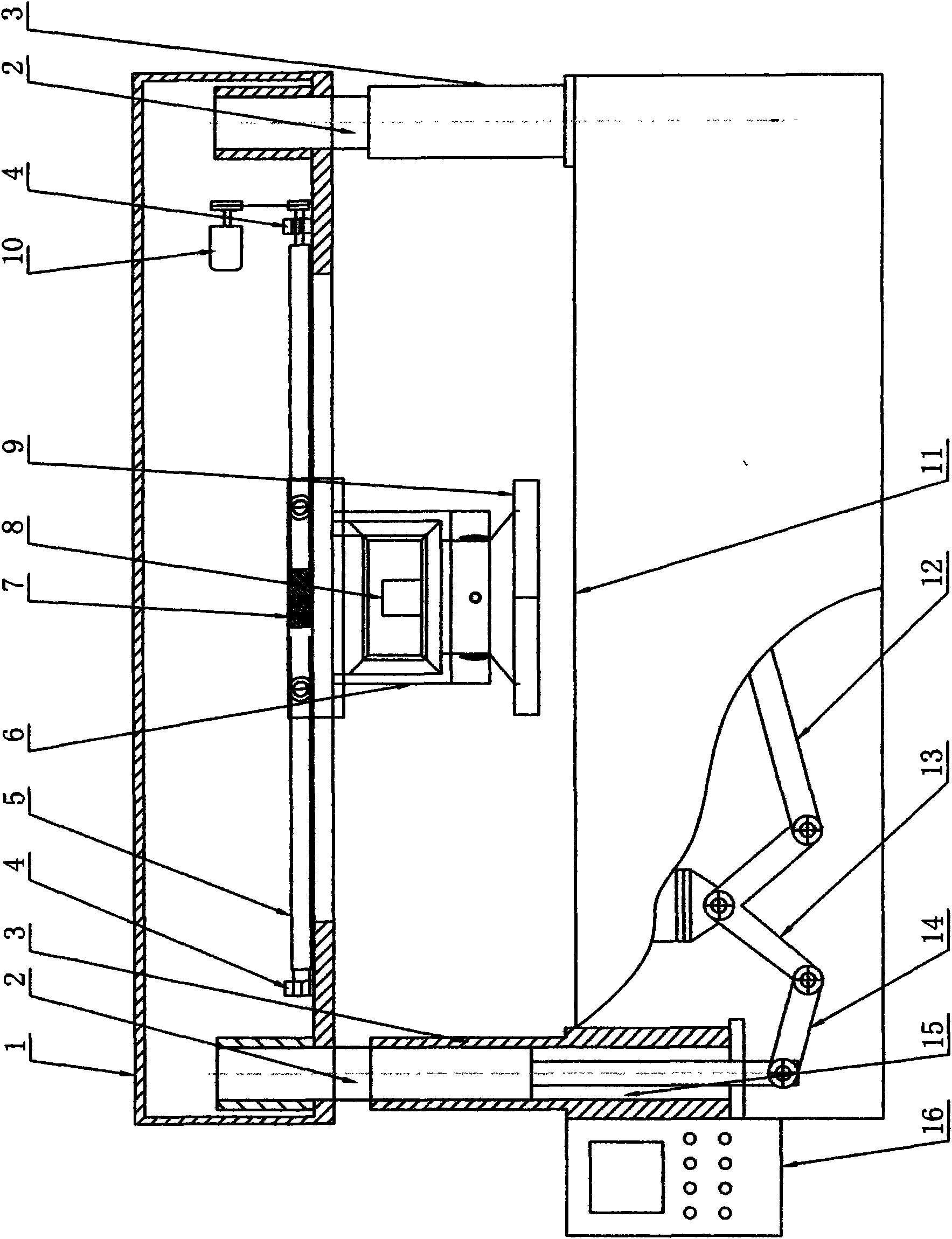
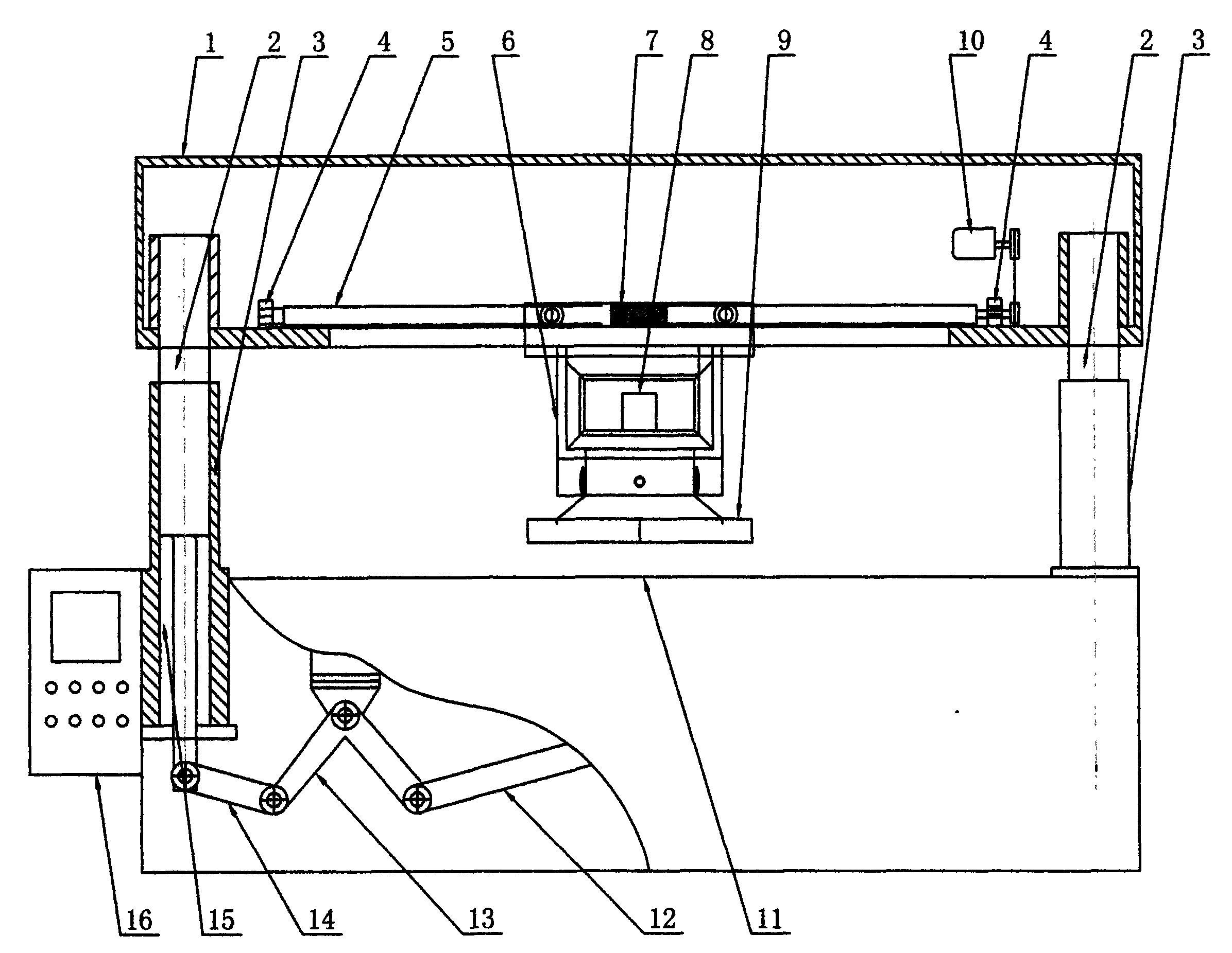
[0011] In the figure: the upper workbench 1 is a rectangular shape, two guide pillars 2 are arranged at the center of the two tops of the bottom surface to connect with the two guide sleeves 3 above the workbench 11, and the upper workbench 1 is provided with a ball screw 5 inside, The screw support base 4 is arranged on the two top ends of the ball screw 5, and the ball screw 5 protrudes from one end of the screw support base 4, and a sprocket is provided on the sprocket, and a chain is arranged on the sprocket to connect with the sprocket on the servo motor 10. , the upper end of the numerically controlled moving head 6 is provided with a connecting seat 7, the connecting seat 7 is connected with the ball screw 5, a stepping motor 8 is provided at the center of the numerically controlled moving head 6, and a rotary mold base 9 is provided at the lower end of the numerically controlled moving head 6, The top of the rotary mold base 9 is provided with a cutting die, the lower p...


PUM


Abstract

The invention discloses a numerical control cutting machine, which comprises an upper workbench, a guide post, a guide sleeve, a screw support, a ball screw, a numerical control moving head, a connecting seat, a step motor, a rotary die holder, a servomotor, a workbench, a balancing connecting rod, a swing plate, a connecting plate, an oil cylinder, and a numerical control box. The computer programming control technology and a human-computer interface are adopted by the machine, a chain wheel on the servomotor drives a chain wheel on the ball screw through a chain, so that the connecting seat on the ball screw drives the numerical control moving head to advance and retreat in the longitudinal direction to realize mobile cutting; the rotary die holder on the numerical control moving head driven by the step motor can rotate 360 DEG; layout and blanking are carried out digitally; and the computer controls a hydraulic system to push the guide post on the oil cylinder to drive a balance mechanism, so that the upper workbench drives the numerical control moving head ascend and descend to realize automatic cutting. The machine has quick response, high precision, stable mechanical properties, low failure rate, high automation degree, and high production efficiency without waste and ungraded product, is convenient and safe to operate, and obviously saves energy.

Description

technical field [0001] The invention relates to a cutting and blanking machine, in particular to a numerically controlled cutting machine, which is suitable for cutting leather, cloth, rubber and plastic materials in shoemaking, clothing, embroidery and leather industries. Background technique [0002] Referring to the common domestic hydraulic blanking machine, the hydraulic mechanism is used to reciprocate up and down for punching and blanking. The punched materials are manually cut out one by one, stacked into several layers, and placed flat on the workbench. The cutting die is placed flat on the material to be blanked, and the cutting die is moved left and right again and again for blanking. Not only is the speed slow, the work efficiency is low, the labor intensity is high, and the raw materials for blanking are wasteful. The most important thing is It is not safe, and if you are not careful, sometimes the operator's hand will be bruised. This kind of cutting machine can ...

Claims


Application Information

Patent Timeline
Patent Type & Authority Applications(China)
IPC IPC(8): B26F1/38B26F1/44
Inventor 陆存林
Owner 陆存林
Why Eureka
Try Eureka