Micro-channel tubular heat exchanger for dehumidification and dehumidifier

A micro-channel and heat exchanger technology, applied in refrigerators, tubular elements, heat exchange equipment, etc., can solve the problems of high manufacturing cost of dehumidifiers, unfavorable for condensed water removal, etc., to improve the removal effect, improve performance, reduce The effect of manufacturing cost

Inactive Publication Date: 2011-03-23
GREE ELECTRIC APPLIANCES INC
View PDF0 Cites 10 Cited by
  • Summary
  • Abstract
  • Description
  • Claims
  • Application Information

AI Technical Summary

Problems solved by technology

The use of finned tube evaporators on dehumidifiers is not conducive to the removal of condensed water, and with the rise in copper prices, the manufacturing cost of dehumidifiers is getting higher and higher

Method used


Image

  • Micro-channel tubular heat exchanger for dehumidification and dehumidifier
  • Micro-channel tubular heat exchanger for dehumidification and dehumidifier
  • Micro-channel tubular heat exchanger for dehumidification and dehumidifier

Examples


Embodiment 1

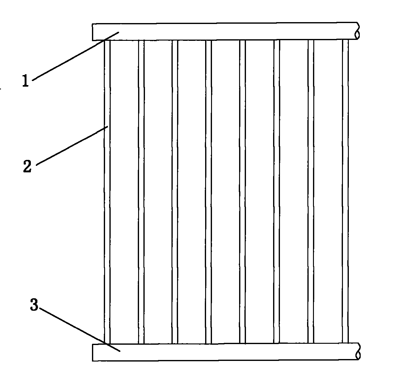
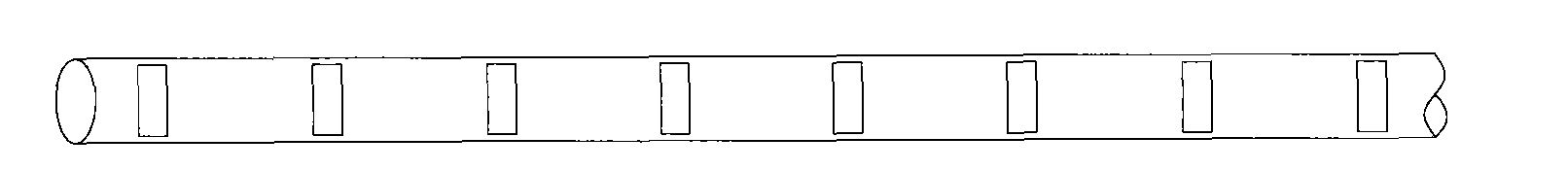
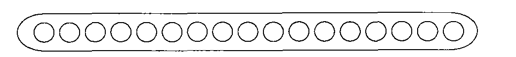
[0030] Such as figure 1 As shown, the microchannel tube heat exchanger for dehumidification in this embodiment consists of an upper header 1, a lower header 3, and several flat tubes 2 arranged between the upper and lower headers, which are parallel to each other and perpendicular to the upper and lower headers. The structural forms of the upper header 1 and the lower header 3 are as follows figure 2 As shown, the figure only shows the case where the header is a round tube. In fact, the header can also be in other forms, such as square tubes, elliptical tubes, and the like. The cross-sectional structural form of the flat tube 3 is as image 3 As shown, the figure only shows the situation that the cross-sectional flow channel is circular, in fact, the cross-sectional flow channel can also be in other forms, such as square, triangular, etc.

[0031] When the microchannel tube heat exchanger for dehumidification is used in a dehumidifier heat exchanger, the refrigerant gas-liq...

Embodiment 2

[0033] Such as Figure 4 As shown, the microchannel tube heat exchanger for dehumidification in this embodiment is based on Embodiment 1, and one or more liquid drainage spacers 4 are arranged obliquely on the flat tube 2, and the liquid drainage spacers 4 can be such as Distance or non-equidistant distribution, this embodiment is equidistant distribution. For the relative position of the drain spacer 4 and the flat tube 2 see Figure 5 , Figure 5 Among them, the liquid drainage spacer 4 forms a certain angle θ with the horizontal position (0<θ<90°), and the liquid drainage spacer 4 is always located on the leeward side of the microchannel tube heat exchanger. In this way, the condensed water condensed on the flat tube 2 flows down along the flat tube 2 under the action of gravity, and when the condensed water reaches the drain spacer 4, the condensed water will flow down The liquid spacer 4 flows down, that is, the drainage spacer 4 can reduce the amount of condensed wate...

Embodiment 3

[0035] Such as Figure 6 As shown, the microchannel tube heat exchanger for dehumidification, its upper header includes a gas collector assembly 5 and a liquid pipe assembly 6; the microchannel tube heat exchanger for dehumidification also includes a lower header 3 and several flat tubes 2 composition; the air collecting pipe assembly 5 such as Figure 7 As shown, the air collecting pipe assembly 5 in the figure is composed of an air collecting pipe 51 and an air collecting branch pipe 52. The air collecting pipe assembly 5 is located on the top of the flat pipe 2; Wherein the cross-sectional view of the gas-collecting branch pipe 52 and the connection part of the flat pipe 2 is as follows: Figure 9 As shown, the top of the flat tube 2 communicates with the gas collecting branch pipe 52 . Figure 7 What is shown in is only one form of air collecting pipe assembly, in fact, it can also be in other forms. The dispenser assembly 6 see Figure 8 As shown, what is shown in the...


PUM


Abstract

The invention discloses a micro-channel tubular heat exchanger for dehumidification, which comprises an upper header, a lower header and a heat exchange tube, wherein the heat exchange tube is arranged between the upper header and the lower header and communicated with the inner chambers of the upper header and the lower header; the heat exchange tube is arranged perpendicular to the upper header and the lower header and comprises more than one oblate tube, and more than one refrigerant flow channel is arranged in the inner chamber of each oblate tube; and the bottom wall surface of the upper header and the upper wall surface of the lower header are provided with mounting holes of the oblate tubes. The invention also discloses a dehumidifier, and the micro-channel tubular heat exchanger for dehumidification is arranged in the inner chamber of the body of the dehumidifier. Because of not adopting fins as heat exchange components, the micro-channel tubular heat exchanger can be used to improve the discharge effect of condensate water by using the advantage that the micro-channel tubular heat exchanger is beneficial to water draining, thereby improving the performance of the dehumidifier and significantly reducing the production cost at the same time.

Description

technical field [0001] The invention belongs to the technical field of air conditioning, and in particular relates to a microchannel tube heat exchanger and a dehumidifier for dehumidification. Background technique [0002] In the prior art, the evaporator used in the dehumidifier is a traditional finned tube heat exchanger, while the application of the finned microchannel heat exchanger is mostly concentrated in the field of automobile air conditioners and room air conditioner condensers. The use of finned tube evaporators on dehumidifiers is not conducive to the removal of condensed water, and with the rise in copper prices, the manufacturing cost of dehumidifiers is getting higher and higher. Therefore, it is necessary to combine the characteristics of various heat exchangers to design a new heat exchanger for the dehumidifier, which not only reduces the manufacturing cost of the dehumidifier, but also improves the removal of condensed water and improves the performance o...

Claims


Application Information

Patent Timeline
Patent Type & Authority Applications(China)
IPC IPC(8): F25B39/02F28F19/02F28F1/02F24F13/22
Inventor 梁祥飞郑波
Owner GREE ELECTRIC APPLIANCES INC
Why Eureka
Try Eureka