Optical pickup device, optical disc device and focus adjusting method

A technology for an optical pickup device and an optical disc device, which is applied in the directions of recording/reproducing by optical methods, optical discs, and disc-shaped record carriers, etc., can solve the problems of an increase in the proportion of stray light, an increase in the number of parts and costs, and a large-scale optical system, etc. Achieving the effect of suppressing the DC component and simplifying the structure

Inactive Publication Date: 2011-03-23
SANYO ELECTRIC CO LTD
View PDF3 Cites 1 Cited by
  • Summary
  • Abstract
  • Description
  • Claims
  • Application Information

AI Technical Summary

Problems solved by technology

[0007] According to the technique of the above-mentioned Patent Document 1, since it is necessary to accurately align the pinholes at the converging positions of the laser light (signal light) reflected from the target recording layer, there is a problem that it is difficult to adjust the position of the pinholes.
When the pinhole size is increased to facilitate position adjustment, the proportion of stray light passing through the pinhole increases, and signal degradation due to stray light cannot be effectively suppressed
[0008] In addition, according to the technology of Patent Document 2, in order to remove stray light, in addition to disposing two 1 / 2 wavelength plates and polarizing optical elements two by two, two lenses are also required, so the number of parts and cost increase, and there is a problem. Issues where the adjustment of the layout of each component becomes complicated
In addition, space is required for arranging and arranging these components, so there is also a problem of increasing the size of the optical system

Method used


Image

  • Optical pickup device, optical disc device and focus adjusting method
  • Optical pickup device, optical disc device and focus adjusting method
  • Optical pickup device, optical disc device and focus adjusting method

Examples


Embodiment Construction

[0056] Hereinafter, embodiments of the present invention will be described with reference to the drawings.

[0057]

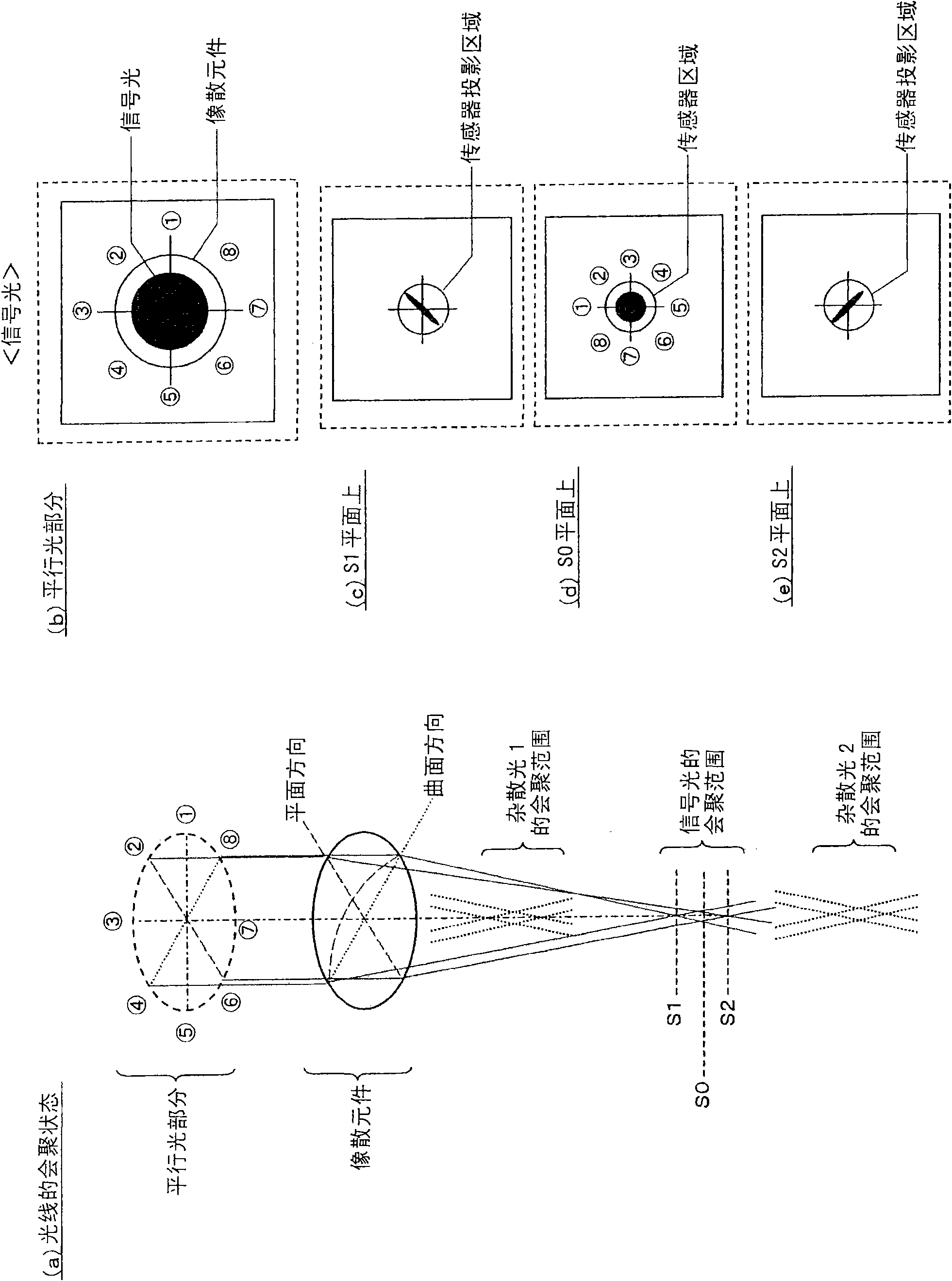
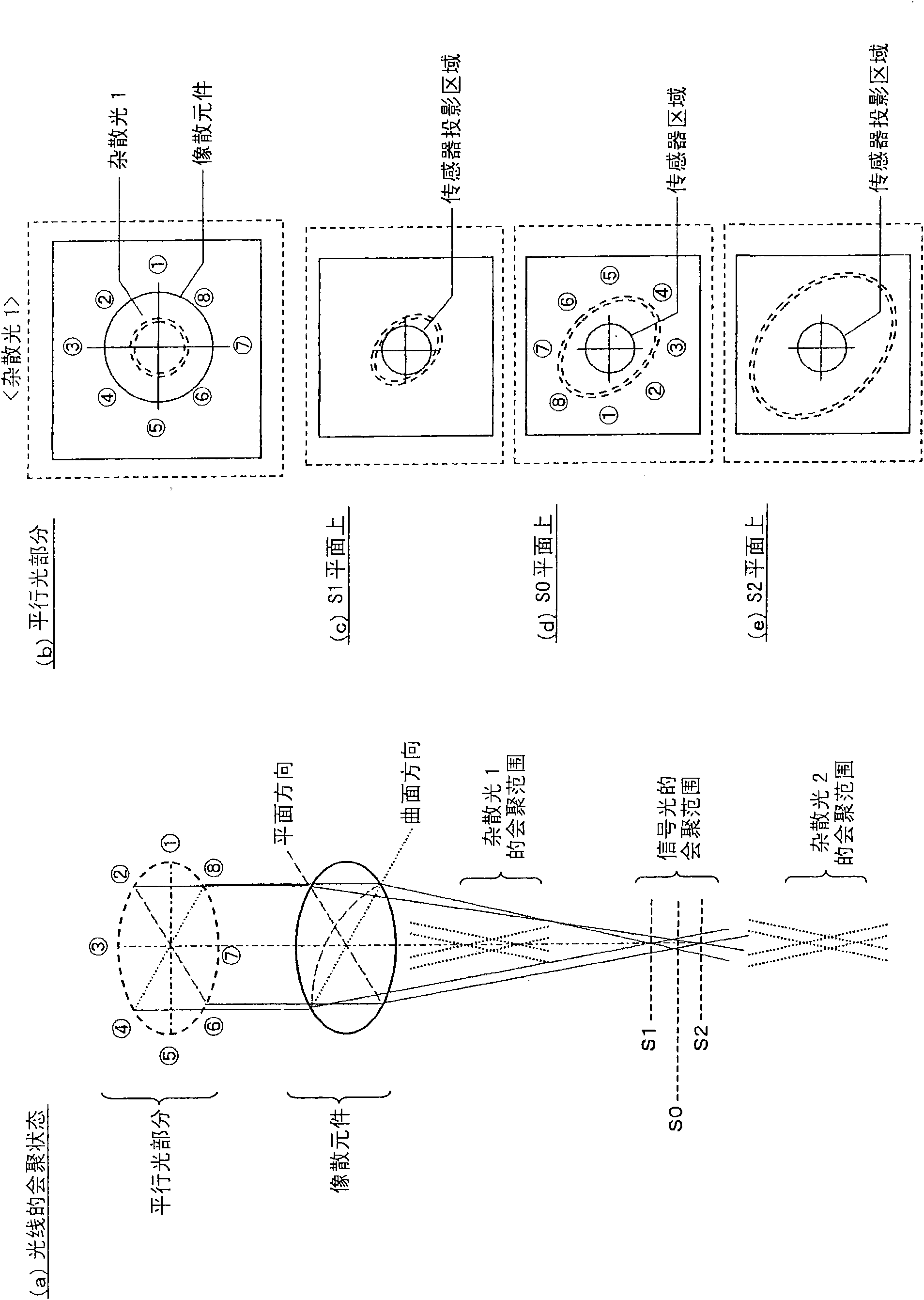
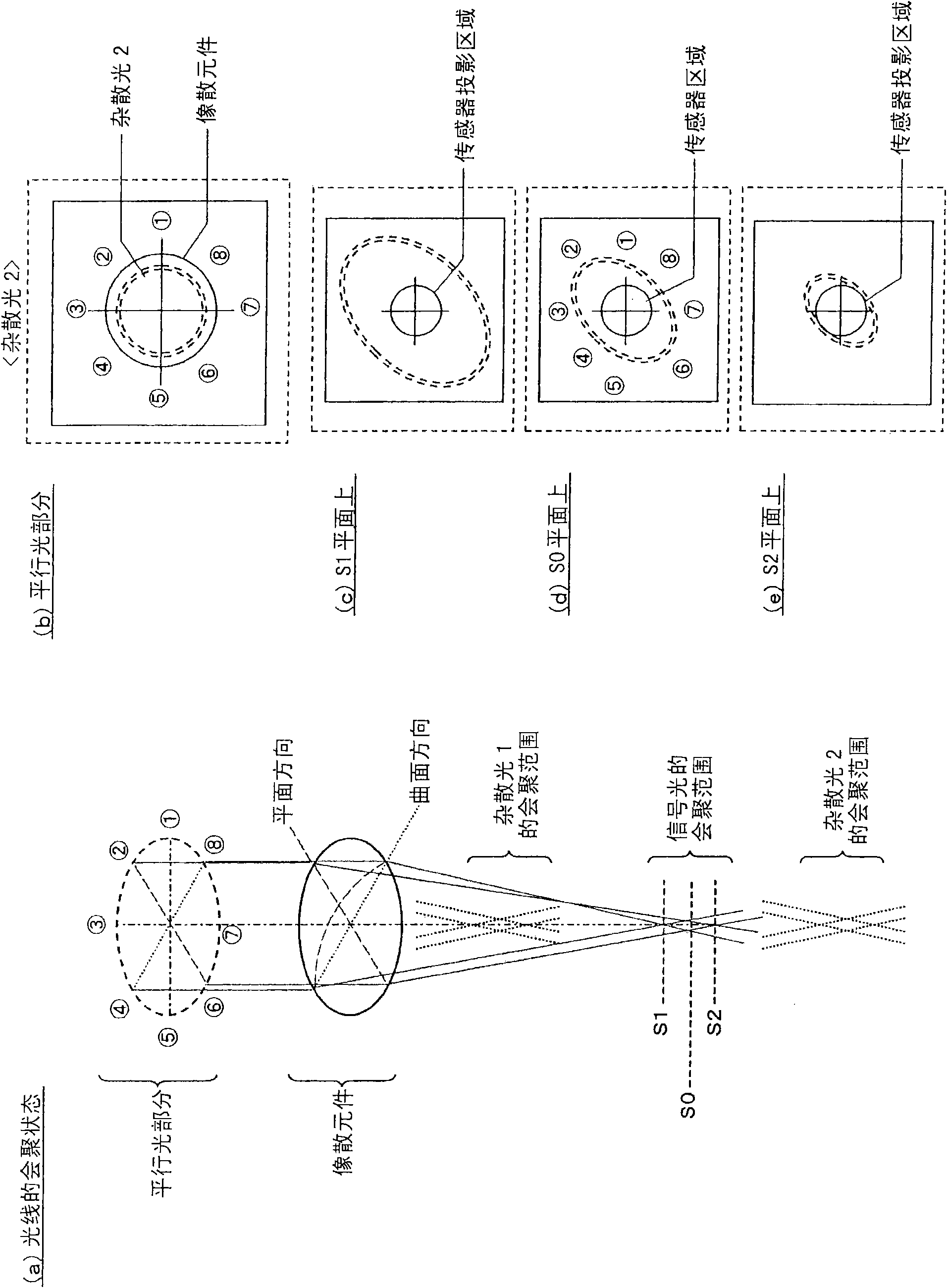
[0058] First, refer to Figure 1 to Figure 10 , to describe the technical principle applied in this embodiment.

[0059] figure 1 (a) is a diagram showing a converging state of signal light and stray light when laser light (signal light) reflected from a target recording layer enters an astigmatic element such as an anamorphic lens in a parallel light state. Among them, viewed from the side of the laser incident surface, "stray light 1" is the laser light reflected by the recording layer that is one layer deeper than the target recording layer, and "stray light 2" is the laser light that is on the outer layer than the target recording layer Laser light reflected by the recording layer. In addition, this figure shows the state when the signal light is focused on the target recording layer.

[0060] As shown in the figure, according to the action of the ana...


PUM


Abstract

The present invention relates to an optical pickup device, an optical disc device, and a focus adjusting method, capable of effectively removing stray light with a simplified arrangement and suppressing a DC component in a tracking error signal. The laser light reflected on the disc is converged on the first direction and the second direction and astigmatism is imparted to the laser light. Propagating directions of four light fluxes are obtained by dividing using two linear lines parallel to the first direction and the second direction and respectively changed into the directions of (Da-Dd). A signal optical area only including the signal light is generated on an optical detector. A sensor pattern is arranged in the area to suppress the infection of the stray light. The correction multiplying power is obtained and for suppressing the DC component of the tracking error signal based on the light quanlity balance of the areas B,C and the about light quanlity of the areas A,D when the laser light is irradiated on a nonorbital testing disc. The tracking error signal is corrected by the correction multiplying power.

Description

technical field [0001] The present invention relates to an optical pickup device, an optical disc device, and a focus adjustment method, and is particularly suitable for application when recording / reproducing a recording medium on which a plurality of recording layers are laminated. Background technique [0002] In recent years, along with the increase in the capacity of optical discs, multi-layer recording layers have been advanced. By including a plurality of recording layers in one disc, the data capacity of the disc can be significantly increased. When stacking recording layers, conventionally, two layers are generally used on one side, but recently, in order to further increase the capacity, arranging three or more recording layers on one side has been studied. Here, increasing the number of stacked recording layers can promote a larger disk capacity. On the other hand, however, the interval between recording layers becomes narrower, and signal degradation due to inte...

Claims


Application Information

Patent Timeline
IPC IPC(8): G11B7/13G11B7/09
CPCG11B2220/2537G11B20/10203
Inventor 金井聪永富谦司
Owner SANYO ELECTRIC CO LTD
Why Eureka
Try Eureka