
System and method for automatically regulating clamping force of motor-driven injection molding machine

A technology of automatic adjustment and adjustment method, which is applied in the field of electric injection molding machines, can solve problems such as unguaranteed mold clamping force, complicated mold adjustment methods, and short life of ball screws.

Inactive Publication Date: 2011-03-30
SOUTH CHINA UNIV OF TECH
View PDF2 Cites 36 Cited by
  • Summary
  • Abstract
  • Description
  • Claims
  • Application Information

AI Technical Summary

Problems solved by technology

[0004] At present, the mold adjustment mechanism of the hydraulic injection molding machine, the hydraulic motor control mold adjustment sensitivity is low, the mold adjustment method is complicated, the mold adjustment accuracy is low, and the accurate mold clamping force cannot be guaranteed after the mold adjustment.
In addition, the generated noise is high and the life of the ball screw is short

Method used


Image

  • System and method for automatically regulating clamping force of motor-driven injection molding machine
  • System and method for automatically regulating clamping force of motor-driven injection molding machine
  • System and method for automatically regulating clamping force of motor-driven injection molding machine

Examples


Embodiment Construction

[0057] The present invention will be further described below with reference to the drawings and embodiments.

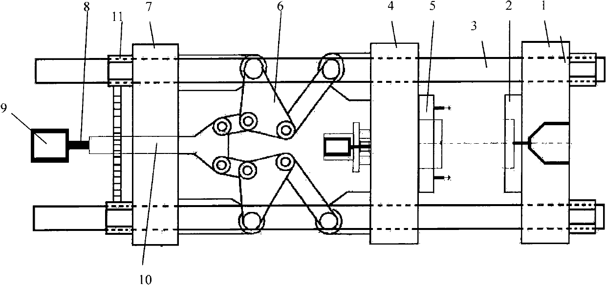
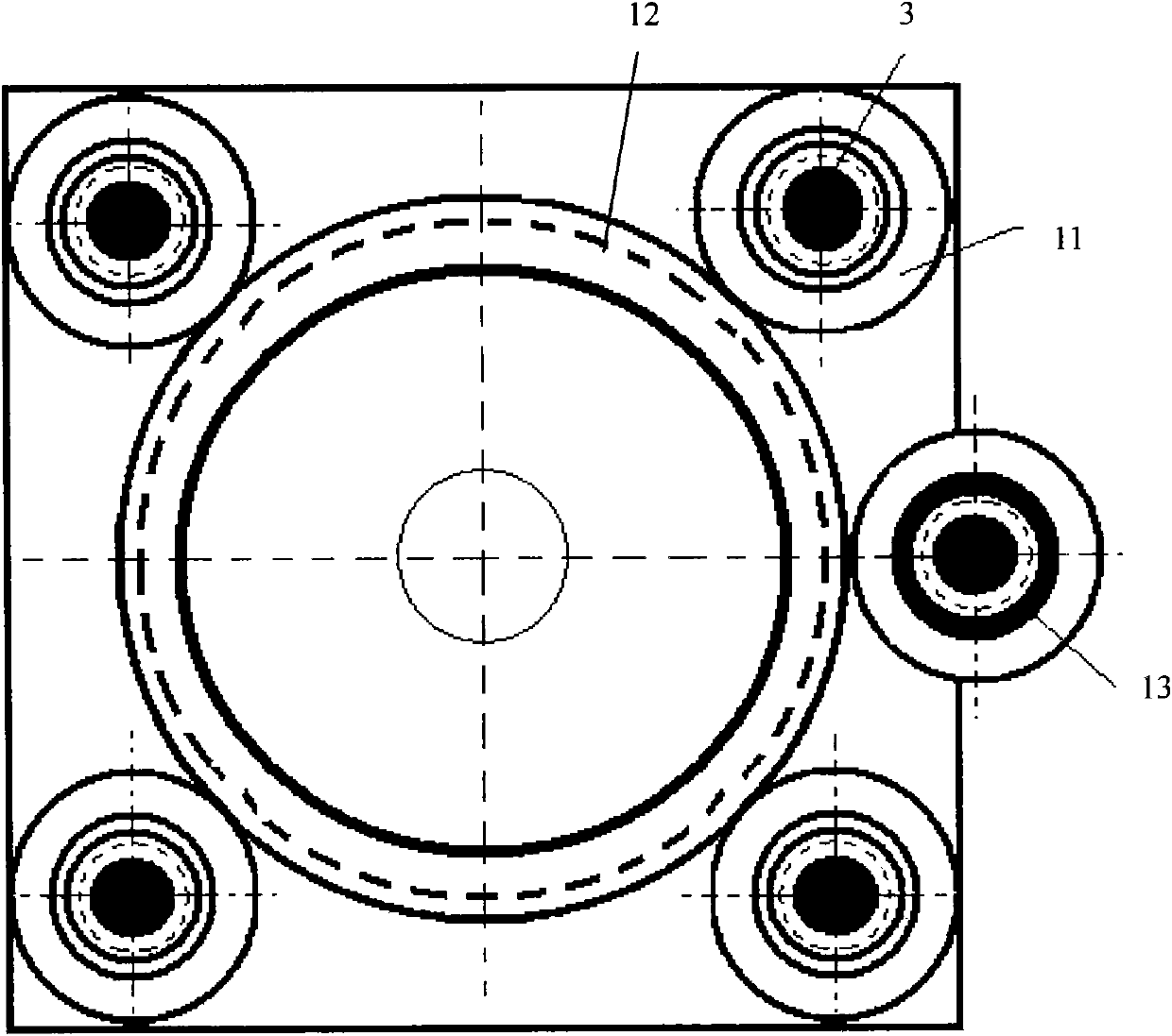
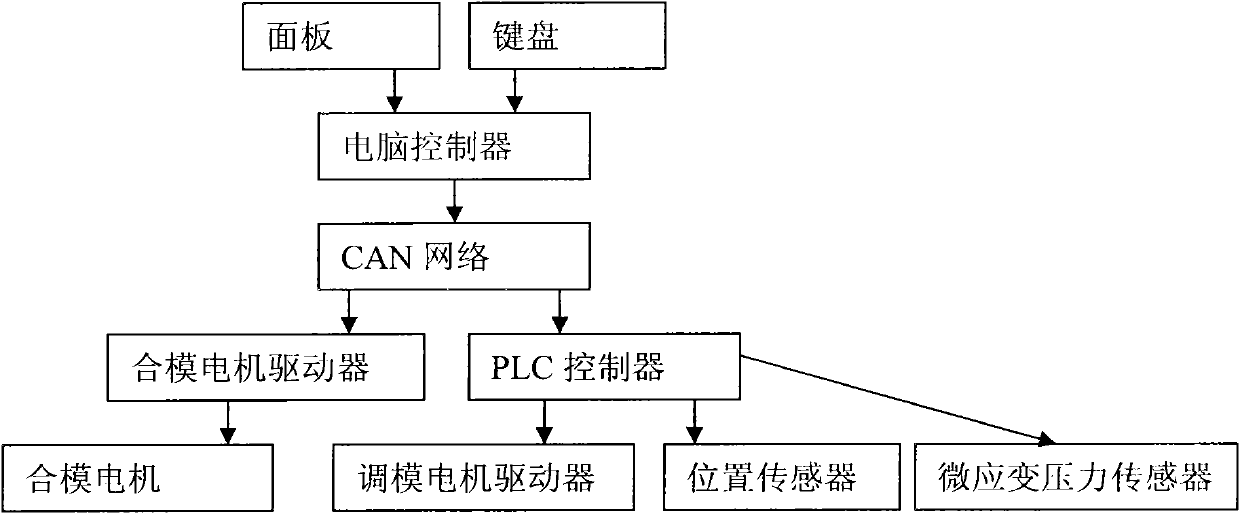
[0058] Such as figure 1 with figure 2 The automatic adjustment system of the clamping force of the electric injection molding machine shown includes the static template 1, the female mold 2, the four tie rods 3, the movable template 4, the male mold 5, the five-point toggle mechanism 6, the rear template 7, and the ball wire Rod 8, mold clamping motor 9 and mold adjustment motor, four tie rods pass through the static template, the dynamic template, and the rear template. The static template is fixed on the tie rods, the female mold is fixed on the static template, and the male mold is fixed on the movable template. The point toggle mechanism is connected between the movable template and the rear template. The cross head 10 of the five-point toggle mechanism passes through the rear template and is sheathed outside the ball screw. The ball screw is driven by the mold clam...


PUM


Abstract

The invention discloses a system for automatically regulating the clamping force of a motor-driven injection molding machine. The system is characterized in that four draw bars penetrate through a static template, a movable template and a rear template, and the static template is fixed on the draw bar; a five-point toggle mechanism is connected between the movable template and the rear template, and the crosshead thereof penetrates through the rear template and is sleeved outside a ball screw; the ball screw is driven by a spotting motor; the rear template is connected with the four draw bars through four regulating nuts; a bearing is arranged between each regulating nut and the rear template; the peripheries of the regulating nuts are provided with gear teeth; a rack wheel is arranged at the neutral position of the four regulating nuts and is meshed with the gear teeth of the four regulating nuts; the crosshead of the five-point toggle mechanism and the ball screw pass through the center of the rack wheel; the output gear of a mold-adjustment motor is meshed with the rack wheel; and the mold-adjustment motor is connected with an injection molding machine control system. The invention also aims at providing a method for automatically regulating the clamping force of a motor-driven injection molding machine. The invention has the advantages that the mold-adjustment accuracy is high.

Description

Technical field [0001] The invention relates to the field of electric injection molding machines, in particular to an automatic adjustment system and adjustment method of the clamping force of the electric injection molding machine. Background technique [0002] The opening and closing of the electric injection molding machine uses a servo motor to drive the crosshead movement through a ball screw. The crosshead and the toggle mechanism transform the rotary motion into linear movement in the direction of mold opening and closing. In the injection and pressure holding stage, the pressure generated by the material in the cavity is called the expansion force. In order to prevent the mold from being separated by the expansion force, the machine must apply sufficient clamping force to the mold. If the clamping force is insufficient, it will cause the mold to separate from the seam and cause flashing, but if it is too large, it will deform the mold, shorten the service life, and cause ...

Claims


Application Information

Patent Timeline
Patent Type & Authority Applications(China)
IPC IPC(8): B29C45/76
Inventor 钟汉如
Owner SOUTH CHINA UNIV OF TECH
Learn More