Electromagnetic drive underground high-power resonant wave displacement device and method

An electromagnetic drive and resonant wave technology, which is applied to vibration generating devices, earthwork drilling, wellbore/well components, etc., can solve the problems of limiting the popularization and application of vibration oil production technology, unstable working conditions, and inconspicuous vibration effects, etc., to achieve Promote the effect of comprehensive oil displacement, facilitate control and adjustment, and improve energy utilization and work efficiency

Active Publication Date: 2011-03-30
CHINA UNIV OF PETROLEUM (EAST CHINA)
View PDF6 Cites 13 Cited by
  • Summary
  • Abstract
  • Description
  • Claims
  • Application Information

AI Technical Summary

Problems solved by technology

[0002] In recent decades, the research and application of vibratory oil recovery technology at home and abroad has progressed rapidly, and a series of supporting equipment and process technology have been formed. The device converts continuous rotating mechanical energy into low-frequency vibration energy. Therefore, in act...

Method used


Image

  • Electromagnetic drive underground high-power resonant wave displacement device and method
  • Electromagnetic drive underground high-power resonant wave displacement device and method
  • Electromagnetic drive underground high-power resonant wave displacement device and method

Examples


Embodiment Construction

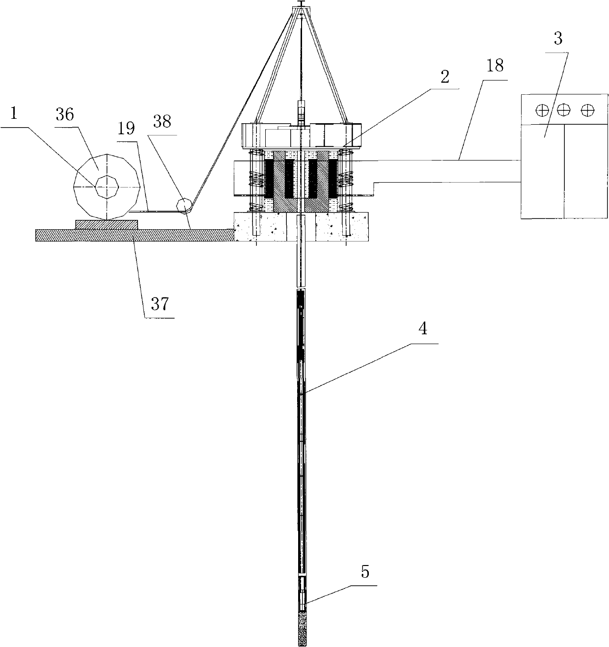
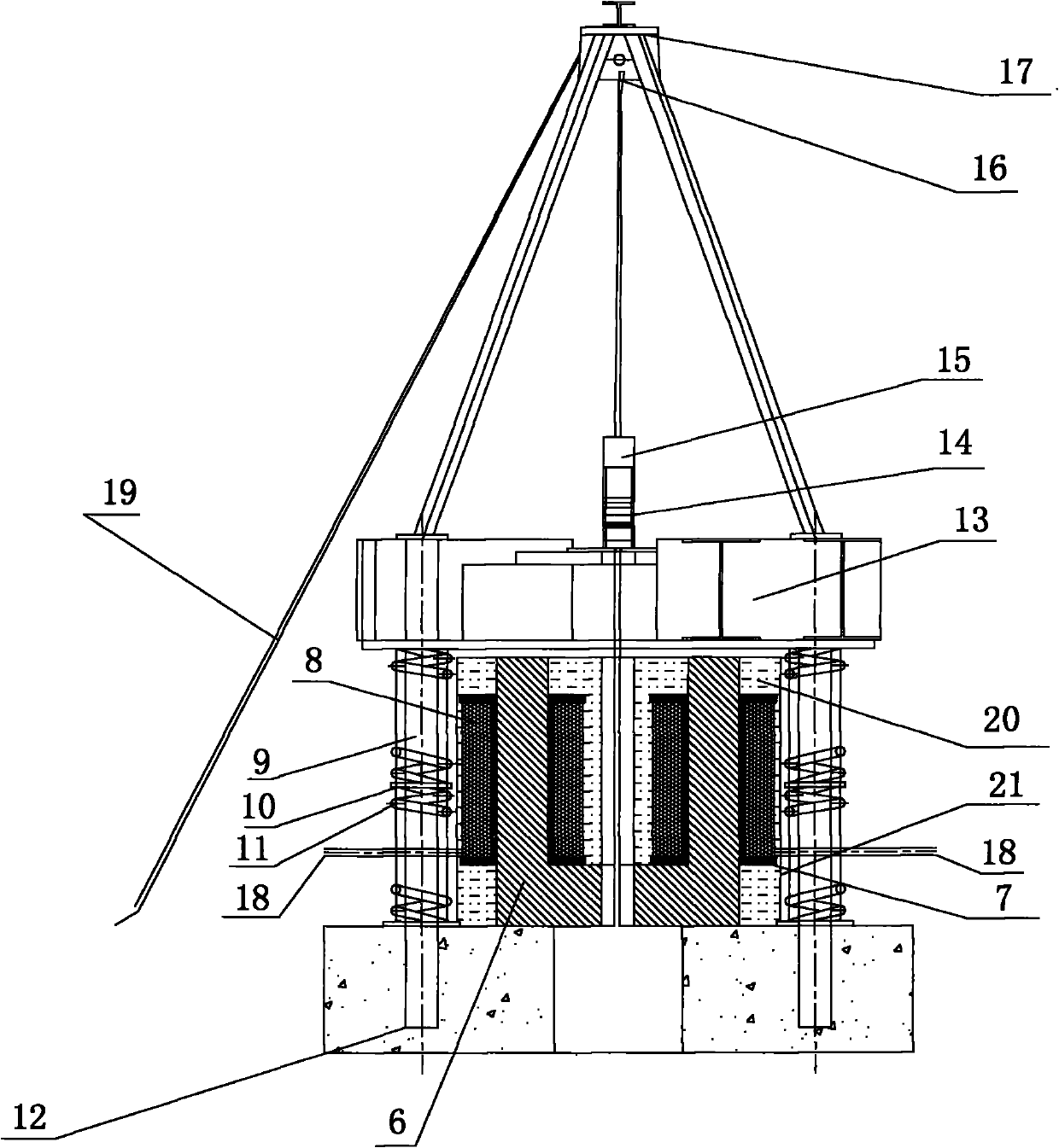
[0048] Such as figure 1 , figure 2 An electromagnetically driven downhole high-power harmonic wave flooding device shown includes a ground vibration source 2 arranged directly above the wellhead of the source well, an artificial well bottom 5 arranged at the bottom of the source well, and vertically inserted from top to bottom. The downhole vibrator 4 inserted into the artificial well bottom 5 in the source well, the downhole vibrator 4 is located directly above the artificial well bottom 5 and the ground vibration source 2 is located directly above the downhole vibrator 4 . The ground vibration source 2 is an electromagnetic vibrator that drives the downhole vibrator 4 to vibrate up and down, and the upper end of the downhole vibrator 4 is fixed on a steel wire rope. Described electromagnetic vibrator comprises the vibrating table 13 that synchronously drives downhole vibrator 4 to vibrate up and down during the vibration process, the excitation coil 8-1 connected with the ...


PUM


Abstract

The invention discloses electromagnetic drive underground high-power resonant wave displacement device and method. The displacement device comprises a ground vibration source, an artificial well bottom and an underground vibrator, wherein the ground vibration source is distributed at the right upper part of a well opening of a vibration source well; the artificial well bottom is distributed at the well bottom of the vibration source well; the underground vibrator is vertically inserted into the vibration source well from top to bottom; the ground vibration source is an electromagnetic vibrator which drives the underground vibrator to vibrate up and down; and a front rope end of a steel rope is fixed to the upper end part of the underground vibrator after penetrating through a central through hole of the ground vibration source from top to bottom, and the steel rope is tightly connected with the ground vibration source. The displacement method comprises the following steps of: 1. selecting the vibration source well; 2. positioning equipment; 3. adjusting a working parameter of the ground vibration source; and 4. carrying out underground vibration displacement by adopting a resonantwave. The invention has the advantages of reasonable design and good construction effect, is convenient for installation and distribution and simple and convenient for use and operation, directly converts electric energy into vibration mechanical energy with stable frequency and stable energy by utilizing an electromagnetic device and greatly improves crude oil yield when reducing the saturation of residual oil.

Description

technical field [0001] The invention belongs to the technical field of downhole vibration oil displacement, and in particular relates to an electromagnetically driven downhole high-power resonance wave oil displacement device and an oil displacement method. Background technique [0002] In recent decades, the research and application of vibratory oil recovery technology at home and abroad has progressed rapidly, and a series of supporting equipment and process technology have been formed. The device converts continuous rotating mechanical energy into low-frequency vibration energy. Therefore, in actual use, existing vibration flooding devices usually have defects and deficiencies such as low equipment power, unstable working conditions, non-concentrated energy, and inconspicuous vibration effects. And the scope of application is relatively narrow, thereby limiting the further popularization and application of vibration recovery technology. Contents of the invention [000...

Claims


Application Information

Patent Timeline
IPC IPC(8): E21B28/00E21B43/25
Inventor 蒲春生张更吴飞鹏
Owner CHINA UNIV OF PETROLEUM (EAST CHINA)
Why Eureka
Try Eureka