
Light communication module

An optical communication module and optical axis technology, applied in the direction of coupling of optical waveguides, can solve the problems of reducing the communication function, the difference is large, and the light cannot be separated correctly, so as to prevent the decline of the communication accuracy and improve the separation accuracy.

Inactive Publication Date: 2011-03-30
ALPS ALPINE CO LTD
View PDF5 Cites 0 Cited by
  • Summary
  • Abstract
  • Description
  • Claims
  • Application Information

AI Technical Summary

Problems solved by technology

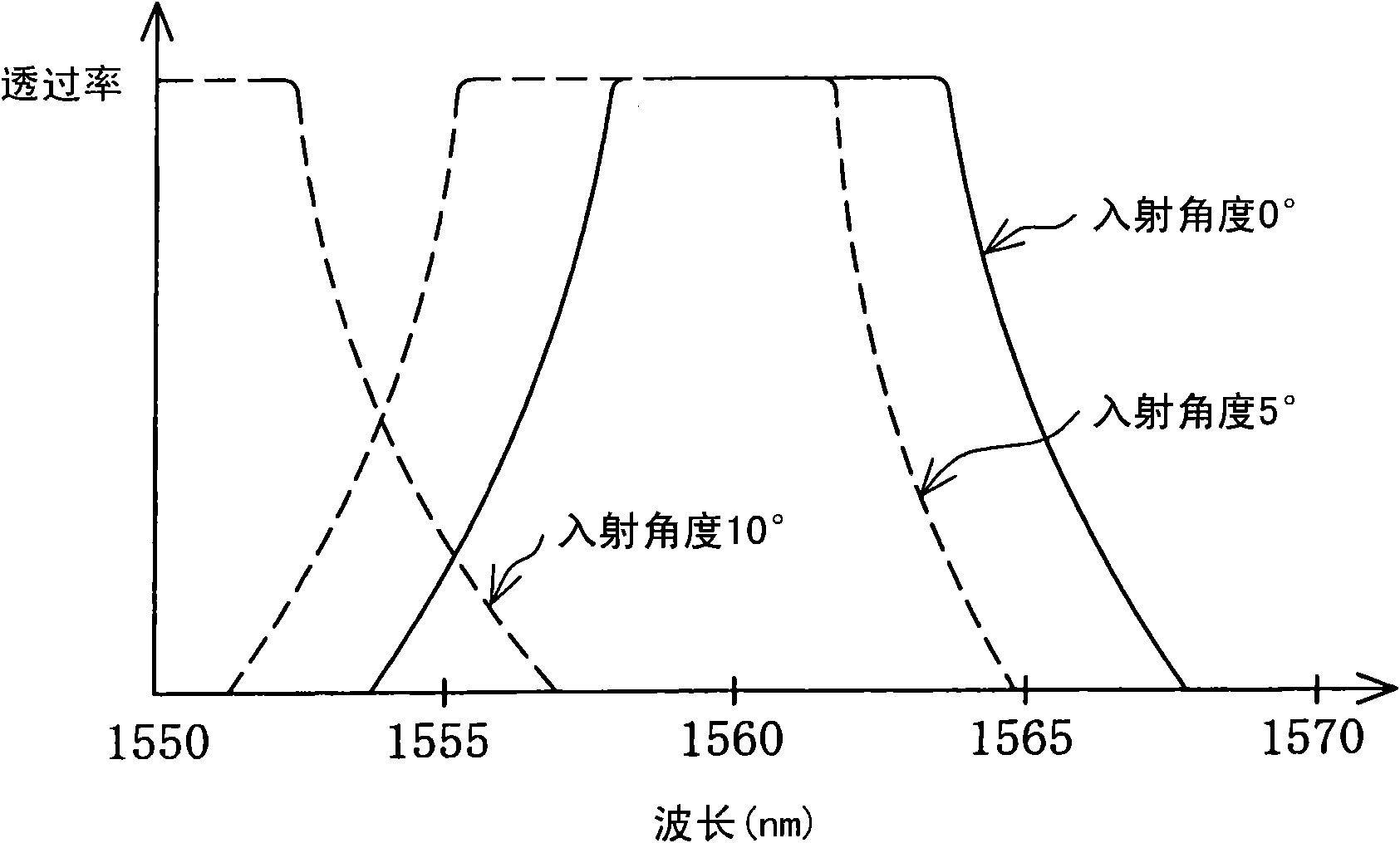
If the incident angle differs so much, the wavelength bands transmitted through the bandpass filter will also vary greatly, and the light cannot be separated correctly, and the transmitted light contains light of a wide range of wavelengths, so there is a problem of degrading the communication function.

Method used


Image

  • Light communication module
  • Light communication module
  • Light communication module

Examples


Embodiment Construction

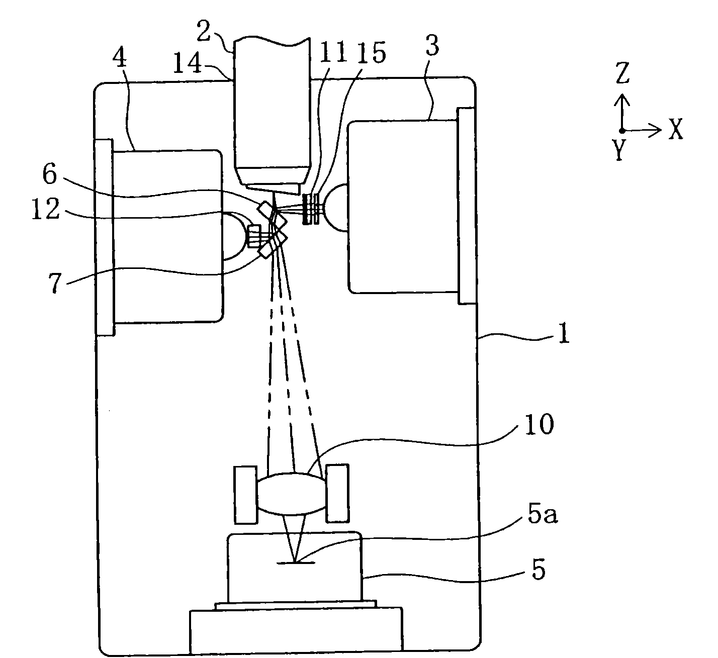
[0036] Embodiments of the present invention will be described in detail below with reference to the accompanying drawings. figure 1 It is a schematic diagram showing the optical communication module of the first embodiment. The optical communication module of the first embodiment is a module that transmits and receives light with the optical fiber 2, and the first light receiving element 3 and the second light receiving element 3 that receive the light emitted by the optical fiber 2 and perform photoelectric conversion are arranged in the main body 1. An element 4 and a light emitting element 5 for incident light on the optical fiber 2 . The light receiving elements 3 and 4 are composed of photodiodes, and the light emitting element 5 is composed of a laser diode.

[0037] A mounting portion 14 for fixing the optical fiber 2 is provided on the main body portion 1 . The light-emitting element 5 is fixed in such a manner that the light-emitting part 5a is disposed at a positio...


PUM


Abstract

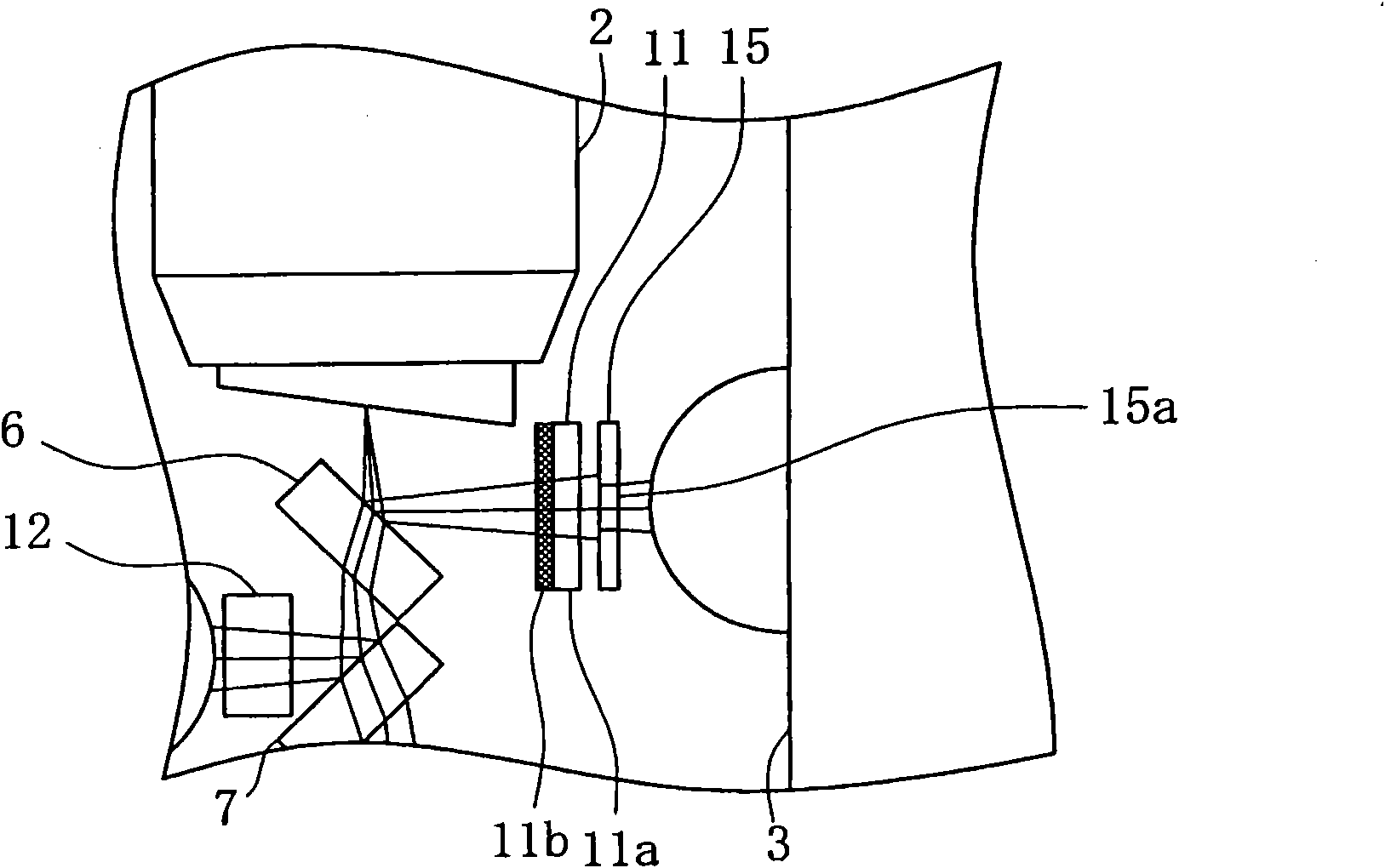
The present invention provides a light communication module, capable of reliably separating light based on one destined waveband when divergent light is emitted to a light-receiving element. The light-receiving element (3) is configured that its optical axis is intersected with an optical axis of a light guide fiber (2), a light filter (6) is configured to face to the light guide fiber (2), the light filter (6) reflects light emitted from the light guide fiber (2) to the light-receiving element, a wavelength separation element (11) through which the light of a destined waveband can passes is arranged between the light filter (6) and the light-receiving element (3), and an opening limitation part (15) through which the light of a central area of the divergent light emitted from the light guide fiber (2) can permeated is arranged on a light path between the light guide fiber (2) and the light-receiving element (3).

Description

technical field [0001] The invention relates to an optical communication module for receiving and emitting light with an optical fiber, in particular to an optical communication module that directly injects the light emitted by the optical fiber into a light-receiving element in a state of divergent light. Background technique [0002] The structure of the currently known optical communication module is to receive and transmit light and transmit and receive signals between the optical fiber. The optical communication module includes not only an optical fiber mounting portion, but also a light receiving element that receives light emitted from the optical fiber to photoelectrically convert it, and a light emitting element that emits light and makes the light incident on the optical fiber. [0003] Since the light receiving element and the light emitting element cannot be arranged at the same position on both sides of the optical axis of the optical fiber, the light emitting e...

Claims


Application Information

Patent Timeline
Patent Type & Authority Applications(China)
IPC IPC(8): G02B6/42
Inventor 菊池俊宏龙田惠一大河内研
Owner ALPS ALPINE CO LTD
Learn More