High voltage capacitor chamber with adjacent structure

A technology of high-voltage capacitors and regulators, which is applied in the substation/power distribution device shell, substation/switchgear cooling/ventilation, etc., can solve the problems of low ventilation and cooling efficiency, large power consumption, energy loss, etc., and improve ventilation and cooling Improve efficiency, improve safety and reliability, and reduce energy consumption

Active Publication Date: 2011-03-30
承方
View PDF7 Cites 3 Cited by
  • Summary
  • Abstract
  • Description
  • Claims
  • Application Information

AI Technical Summary

Problems solved by technology

[0002] Substations need to use a large number of high-voltage capacitors, and the high-voltage capacitors are installed in multiple independent high-voltage capacitor rooms. In the prior art, the ventilation and heat dissipation of each high-voltage capacitor room are independent. Fans are used for ventilation and heat dissipation. This independent ventilation and heat dissipation method not only consumes a lot of power, but also generates a lot of other problems.
Because this ventilation method produces negative pressure in the high-voltage capacitor room, outdoor dust and debris can easily enter the high-voltage capacitor room from the air inlet and raise the dust on the ground, causing serious dust accumulation on the high-voltage capacitor. If the indoor air is humid, Dirt creepage and pollution flashover will occur on the surface of high-voltage capacitors, which will bring safety hazards. In addition, because the existing ventilation and cooling methods cause turbulence or mixed flow of airflow in the entire interior space of high-voltage capacitor chambers, the efficiency of ventilation and cooling is low, resulting in A lot of energy consumption, and cause a lot of noise pollution to the surrounding environment

Method used


Image

  • High voltage capacitor chamber with adjacent structure
  • High voltage capacitor chamber with adjacent structure
  • High voltage capacitor chamber with adjacent structure

Examples


Embodiment 1

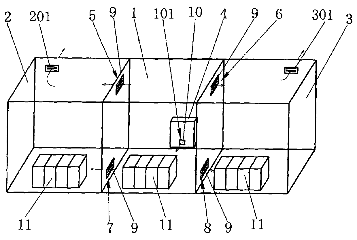
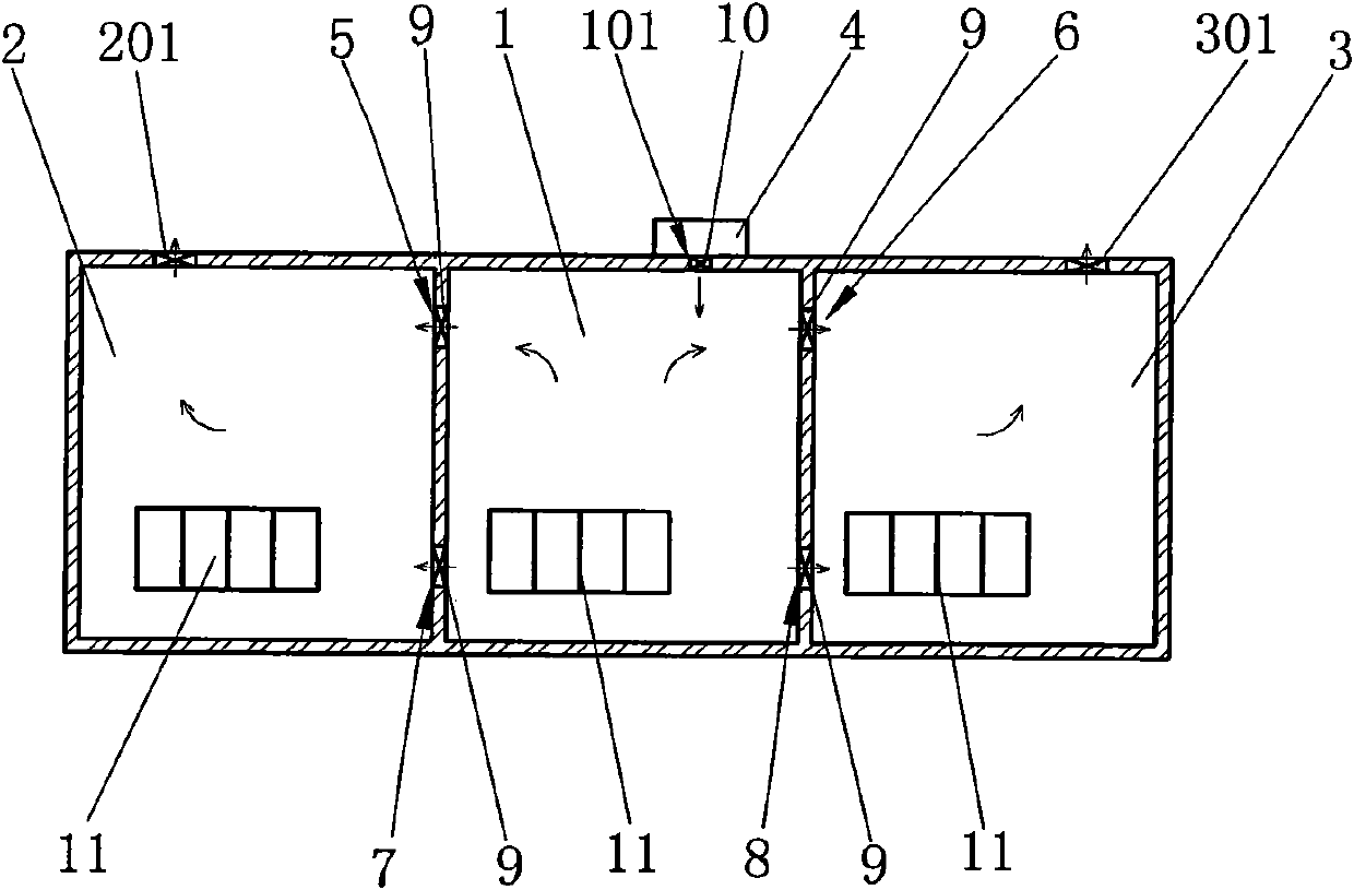
[0015] The present invention comprises at least three machine rooms connected adjacently on the left and right sides, high-voltage capacitors are arranged in the machine room, and the number of rooms in the machine room is determined according to actual needs, such as figure 1 , 2 As shown, in this embodiment, there are three machine rooms adjacently connected to the left and right. The first machine room 1 is the machine room in the middle, and its lower part is provided with an air inlet 101; the second machine room 2 is located on the left side of the first machine room 1, and its upper part An air outlet 201 is provided, and the third machine room 3 is located on the right side of the first machine room 1, and an air outlet 301 is provided on the upper part thereof; The outside of the first computer room 1 is provided with an intelligent temperature-controlled ventilation regulator 4 that supplies air to the computer room. The air outlet of the intelligent temperature-cont...

Embodiment 2

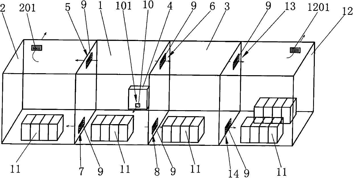
[0019] Such as image 3 As shown, in this embodiment, there are four machine rooms adjacently connected to the left and right. The first machine room 1 is a machine room located in the middle, and the lower part is provided with an air inlet 101; the second machine room 2 is located on the left side of the first machine room 1. The upper part is provided with an air outlet 201, and the lower part of the partition wall between the first machine room 1 and the second machine room 2 is provided with an air inlet communication port 7, and the upper part of the partition wall between the first machine room 1 and the second machine room 2 is air outlet. Connecting port 5; the third machine room 3 and the fourth machine room 12 are located on the right side of the first machine room 1, the fourth machine room 12 is the last machine room on the right side of the first machine room 1, and the upper part of the fourth machine room 12 is provided with an air outlet 1201, The lower part o...


PUM


Abstract

The invention relates to a high voltage capacitor chamber with an adjacent structure. The high voltage capacitor chamber comprises at least three machine rooms which are adjacently connected with each other along the leftward and rightward direction, and is characterized in that the lower part of one machine room on the middle part is provided with an air inlet, wherein the upper parts of the final machine rooms on the left side and the right side are provided with air outlets; an intelligent temperature control ventilation adjuster for supplying air into the room machine is arranged outside the machine room at the middle part and connected with the air inlet; the upper part of a partition wall of two adjacent machine rooms is provided with an air outlet communication port and the lower part of the partition wall is provided with an air inlet communication port; and both the air outlet communication port and the air inlet communication port are provided with bidirectional explosion and fire protection valves. One intelligent temperature control ventilation adjuster is used for simultaneously ventilating and cooling a plurality of high voltage capacitor chambers which are connected adjacently, and controllable small-volume and low-speed air flow is used for ventilating and cooling the high voltage capacitor chamber, so that turbulence or mixed flow of the air flow in the high voltage capacitor chamber is not caused, the ventilating and cooling efficiency is improved, the energy consumption is greatly reduced, and the noise pollution to peripheral environment is eliminated.

Description

technical field [0001] The invention relates to a high-voltage capacitor room, in particular to a high-voltage capacitor room with an adjacent structure. Background technique [0002] Substations need to use a large number of high-voltage capacitors, and the high-voltage capacitors are installed in multiple independent high-voltage capacitor rooms. In the prior art, the ventilation and heat dissipation of each high-voltage capacitor room are independent. Fans are used for ventilation and heat dissipation. This independent ventilation and heat dissipation method not only consumes a lot of power, but also generates a lot of other problems. Because this ventilation method produces negative pressure in the high-voltage capacitor room, outdoor dust and debris can easily enter the high-voltage capacitor room from the air inlet and raise the dust on the ground, causing serious dust accumulation on the high-voltage capacitor. If the indoor air is humid, Dirt creepage and pollution ...

Claims


Application Information

Patent Timeline
Patent Type & Authority Applications(China)
IPC IPC(8): H02B1/56H02B1/26
Inventor 承方
Owner 承方
Why Eureka
Try Eureka