
Glass assembly cutting method, package manufacturing method, package, piezoelectric vibrator, oscillator, electronic device, and radio-controlled timepiece

A piezoelectric vibrator and packaging technology, which is applied in the field of radio clocks, can solve problems such as rough cut surfaces, low yields, and fractures of wafer joints, and achieve the effects of improving surface accuracy, increasing yields, and high reliability

Inactive Publication Date: 2011-04-06
SEIKO INSTR INC
View PDF3 Cites 4 Cited by
  • Summary
  • Abstract
  • Description
  • Claims
  • Application Information

AI Technical Summary

Problems solved by technology

[0005] However, in the cutting method using a cutter, it is necessary to provide a cutting edge (cutting generation) in consideration of the width dimension of the cutter between the formation regions of the piezoelectric vibrator. The number of piezoelectric vibrators is small, and chipping occurs during cutting, and the wafer bonded body is easily broken due to chipping, and the cut surface is rough, etc.
[0007] However, in the above-mentioned method, there is such a problem that since numerous chips are generated in the scribe line, the wafer bonded body is easily broken due to chipping, and the cut surface is also rough.
As a result, there is a problem that the wafer bonded body 203 breaks from a position different from the scribe groove M' (a so-called slipping phenomenon occurs).
[0020] As a result, there is a problem that, in the worst case, the cavity C communicates with the outside and the airtightness in the cavity C cannot be ensured.
These products are treated as defective products, so there is a problem that the number of good products obtained from one wafer bonded body 203 is reduced, and the yield rate is low.

Method used


Image

  • Glass assembly cutting method, package manufacturing method, package, piezoelectric vibrator, oscillator, electronic device, and radio-controlled timepiece
  • Glass assembly cutting method, package manufacturing method, package, piezoelectric vibrator, oscillator, electronic device, and radio-controlled timepiece
  • Glass assembly cutting method, package manufacturing method, package, piezoelectric vibrator, oscillator, electronic device, and radio-controlled timepiece

Examples


Embodiment Construction

[0077] Hereinafter, embodiments of the present invention will be described with reference to the drawings.

[0078] (Piezo Vibrator)

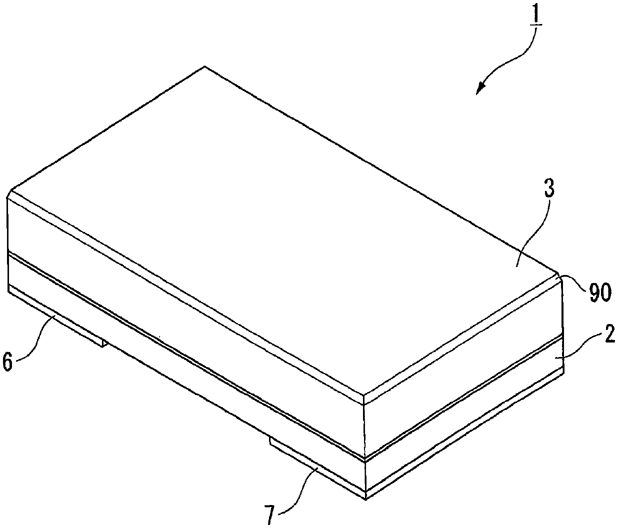
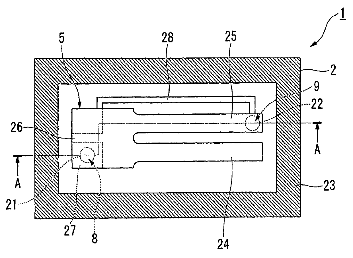
[0079] figure 1 is an external perspective view of the piezoelectric vibrator of this embodiment, figure 2 It is an internal structure diagram of the piezoelectric vibrator, and it is a top view of the piezoelectric vibrating piece with the cover board removed. also, image 3 is along figure 2 A cross-sectional view of the piezoelectric vibrator shown on line A-A, Figure 4 It is an exploded perspective view of the piezoelectric vibrator.

[0080] Such as Figure 1 to Figure 4 As shown, the piezoelectric vibrator 1 is formed in a box shape in which two layers of a base substrate 2 and a lid substrate 3 are stacked, and is a surface-mounted piezoelectric vibrator in which a piezoelectric vibrating reed 5 is housed in a cavity C inside. 1. Further, the piezoelectric vibrating reed 5 is electrically connected to the external electrodes ...


PUM

PropertyMeasurementUnit
wavelengthaaaaaaaaaa
diameteraaaaaaaaaa
wavelengthaaaaaaaaaa

Abstract

Providing a glass assembly cutting method capable of improving yield by cutting a glass assembly into a predetermined size, providing a package manufacturing method, a package and a piezoelectric vibrator manufactured by the manufacturing method, and an oscillator, an electronic device, and a radio-controlled timepiece. Providing a wafer assembly cutting method of cutting a wafer assembly 60 along a scribe line M', the method including: a scribing step of irradiating a laser beam having an absorption wavelength of the wafer assembly 60 along the contour line to form the scribe line M' on a lid board wafer 50; and a breaking step of applying a breaking stress along the scribe line M' using a cutting blade to cut the wafer assembly along the scribe line M', wherein the scribing step involves forming the scribe line M' so that the ratio of a depth dimension D of the scribe line M' to a width dimension W thereof is 0.8 or larger and 6.0 or smaller.

Description

technical field [0001] The present invention relates to a method of cutting bonding glass, a method of manufacturing a package, a package, a piezoelectric vibrator, an oscillator, electronic equipment, and a radio clock. Background technique [0002] In recent years, piezoelectric vibrators (packages) using crystals or the like as time sources, timing sources such as control signals, reference signal sources, and the like have been used in mobile phones and portable information terminal devices. As such a piezoelectric vibrator, various piezoelectric vibrators are known, and as one of them, a surface mount (SMD) type piezoelectric vibrator is known. As such a piezoelectric vibrator, there are, for example: a base substrate and a lid substrate bonded to each other; a cavity formed between the two substrates; and a piezoelectric vibrating piece (electronic component) housed in an airtight state in the cavity. ). [0003] Here, when manufacturing the above-mentioned piezoelec...

Claims


Application Information

Patent Timeline
Patent Type & Authority Applications(China)
IPC IPC(8): C03B33/02H03H3/02H03H9/02H03H9/19G04C9/02H10N30/88B23K26/00B23K26/364B23K26/40B28D5/00C03B33/07C03B33/09C03B33/10H01L23/08
CPCH03H9/21H03H9/1021H01L2224/97Y10T29/49005Y10T29/49798Y10T29/42Y10T29/49126
Inventor 沼田理志
Owner SEIKO INSTR INC
Learn More