
Novel screw expanding power machine

A screw expansion and power engine technology, applied in the direction of engine components, machines/engines, intermeshing engines, etc., can solve the problems of low efficiency and reliability, ignore the research and design of screw expansion power, and the overall performance level is not high, so as to achieve improvement Efficiency, ease of assembly and maintenance, and ease of design

Inactive Publication Date: 2012-07-25
范年宝 +1
View PDF0 Cites 0 Cited by
  • Summary
  • Abstract
  • Description
  • Claims
  • Application Information

AI Technical Summary

Problems solved by technology

[0004] However, most of the existing domestic screw expander manufacturers pay more attention to the system design of waste heat recovery, while ignoring the power research and design of the screw expander power machine
Most unit power machines only partially modify the main engine of ordinary screw compressors, such as reversing the suction port and exhaust port, and use it as an expander, so that the efficiency and reliability of the unit are low, and the overall low performance level

Method used


Image

  • Novel screw expanding power machine
  • Novel screw expanding power machine
  • Novel screw expanding power machine

Examples


Embodiment Construction

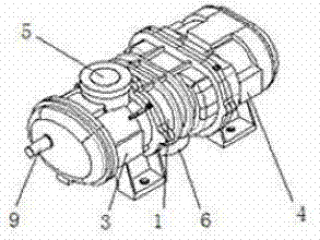
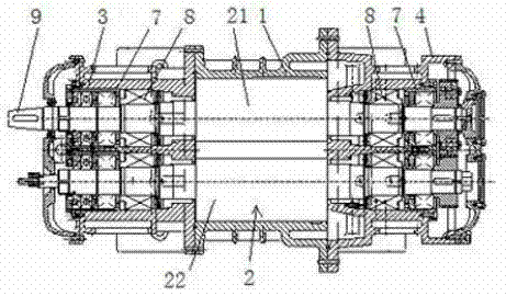
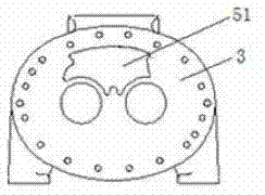
[0024] see figure 1 , figure 2 . The present invention is a novel screw expansion power machine for waste heat recovery working conditions, comprising: cylinder body 1, power machine screw rotor pair 2, suction end seat 3, exhaust end seat 4. The screw rotor pair 2 of the power machine is arranged in the cylinder block, including the male rotor 21 and the female rotor 22 which mesh with each other, and both adopt bilateral symmetrical arc-shaped lines. The suction end seat 3 and the exhaust end seat 4 are respectively arranged at both ends of the cylinder block 1 . Both the suction end seat and the exhaust end seat are designed as a double-wall structure, and cooling water is passed through the interlayer. A suction channel 5 is provided on the suction end seat 3 . An exhaust passage 6 is provided at the lower part of the cylinder block 1 .

[0025] The male rotor 21 and the female rotor 22 of the present invention are carried by bearings, such as figure 2 The central ...


PUM


Abstract

The invention discloses a novel screw expanding power machine, mainly comprising a cylinder block, a power machine screw rotor pair, an air sucking terminal block, and an air exhausting terminal block, wherein the power machine screw rotor pair is arranged in the cylinder block and comprises a male rotor and a female rotor which are intermeshed. The novel screw expanding power machine is characterized in that: a screw rotor adopts bilateral symmetrical arc molded lines; the air sucking terminal block and the air exhausting terminal block are double-wall sandwich structures with cooling water in the sandwich layers; the air sucking terminal block and the air exhausting terminal block are respectively and detachably arranged at two ends of the cylinder block; an air sucking passage is arranged above the air sucking terminal block; an axial air sucking orifice communicated with the air sucking passage is arranged on the air sucking terminal block and a radial air sucking orifice communicated with the air sucking passage is arranged in the cylinder block near the air sucking orifice; an air exhausting passage is arranged at the lower part of the cylinder block; and a radial air exhausting orifice communicated with the air exhausting passage is arranged at the lower interior inside the cylinder block near the air exhausting terminal block. The novel screw expanding power machine has the advantages of reliable motion, convenience for assembling and maintenance, stability in operation, high efficiency, strong adaptability to working conditions, and low vibration and noise.

Description

technical field [0001] The invention relates to a screw expander, in particular to a novel screw expander power machine. Background technique [0002] With the emphasis on energy utilization in our country, more and more energy-saving and energy recycling technologies have been developed. In the production of major industrial and mining enterprises, a large amount of industrial waste heat such as heat, steam, and flue gas will be generated, which is an important secondary energy source. Especially in chemical industry, oil refining, metallurgy, papermaking and other industries, the proportion is very large. With the attention paid to the energy-saving transformation of equipment and the utilization of secondary energy in industrial production, industrial waste heat has begun to be utilized. Among them, the use of expanders to recycle these secondary energy sources is a rapidly developing technology. For a long time, turbo expanders have been widely used in the industry. ...

Claims


Application Information

Patent Timeline
Patent Type & Authority Patents(China)
IPC IPC(8): F01C1/16F01C21/08F01C21/10F01C21/18
Inventor 范年宝范晓军
Owner 范年宝
Learn More