Multi-connected unit phase change energy storage hot liquid defrosting system

A technology of phase change energy storage and hydrothermal defrosting, which is applied in energy recovery systems for ventilation and heating, air conditioning systems, ventilation systems, etc. Slow down and other problems, to improve reliability, speed up defrosting speed, prolong life

Inactive Publication Date: 2011-04-06
HARBIN INST OF TECH
View PDF3 Cites 20 Cited by
  • Summary
  • Abstract
  • Description
  • Claims
  • Application Information

AI Technical Summary

Problems solved by technology

[0005] In order to solve the problems that the current defrosting system needs to absorb heat from the heating room during defrosting, the room temperature drops sharply, the frequent reversing of the four-way reversing valve affects its life during the defrosting process, the defrosting speed is slow, and the energy consumption is large. A multi-phase change energy storage hydrothermal defrosting system is provided

Method used


Image

  • Multi-connected unit phase change energy storage hot liquid defrosting system
  • Multi-connected unit phase change energy storage hot liquid defrosting system

Examples


specific Embodiment approach 1

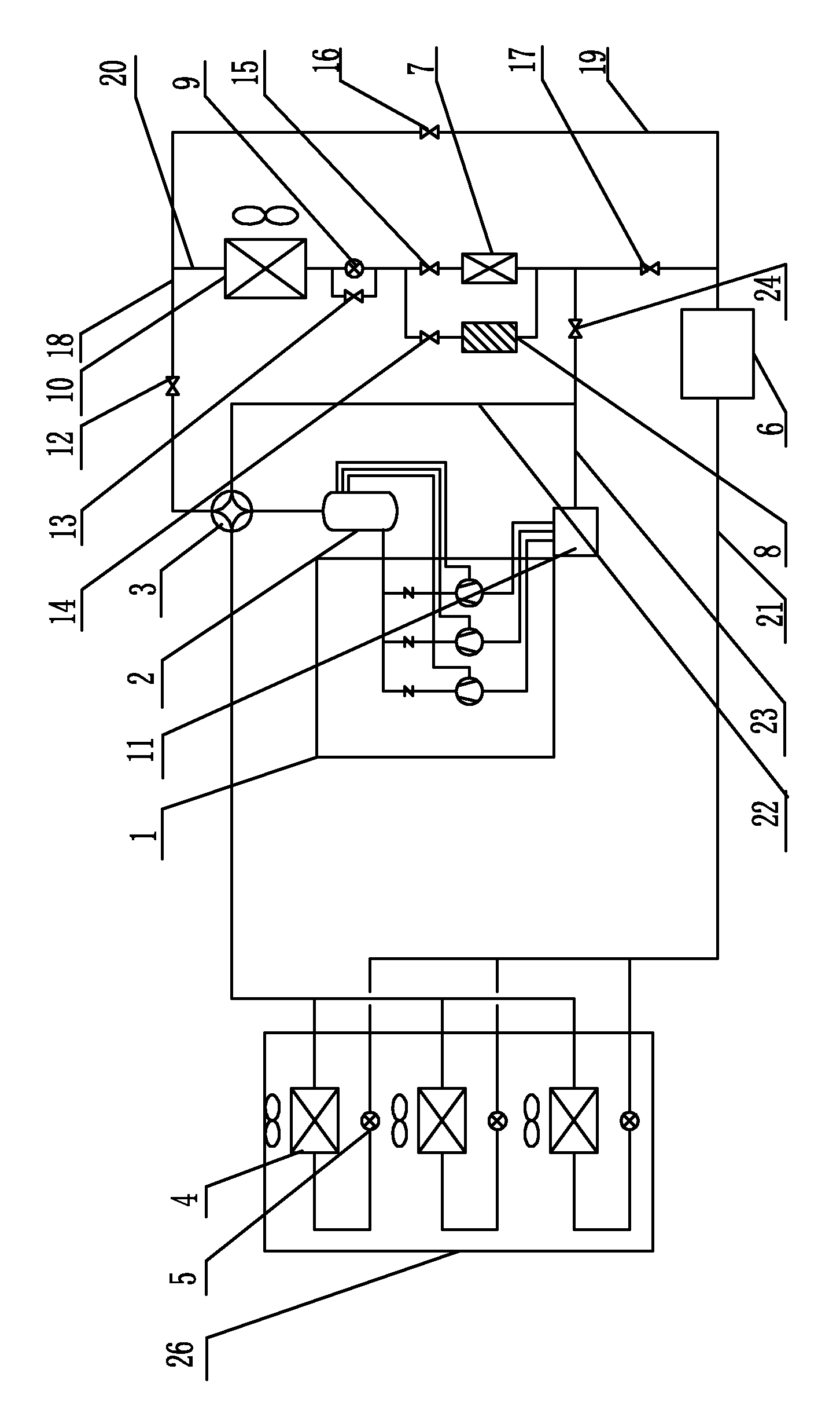
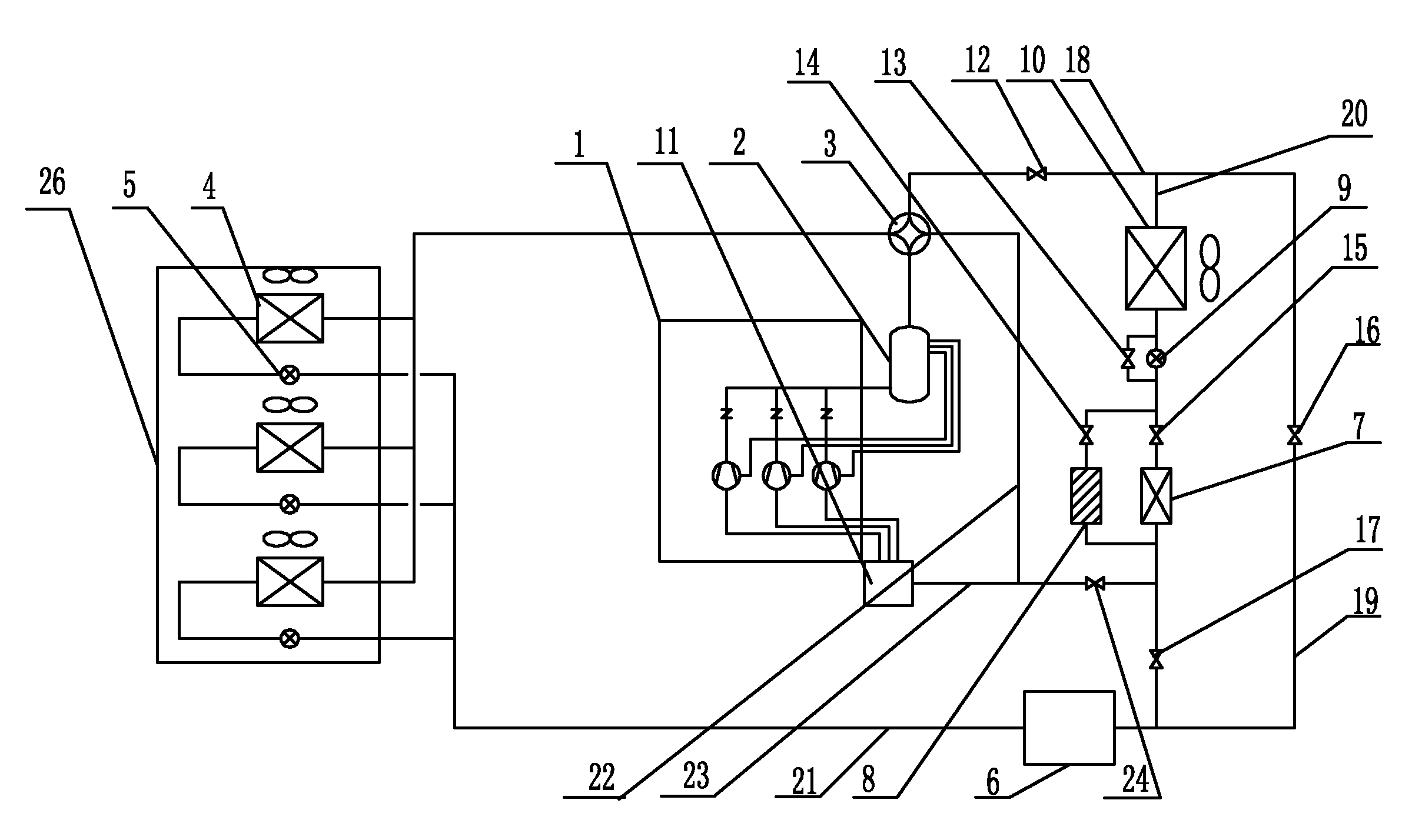
[0009] Specific implementation mode one: combine figure 1 Describe this embodiment. The system of this embodiment includes a compressor unit 1, an oil separator 2, a four-way reversing valve 3, a liquid receiver 6, a subcooler 7, an outdoor electronic expansion valve 9, an outdoor heat exchanger 10, The gas-liquid separator 11 and the indoor unit 26, the outlet end of the compressor unit 1 communicates with the inlet end of the oil separator 2, and the outlet end of the oil separator 2 communicates with one of the through holes of the four-way reversing valve 3, the system It also includes a phase change heat accumulator 8, a first solenoid valve 12, a second solenoid valve 13, a third solenoid valve 14, a fourth solenoid valve 15, a fifth solenoid valve 16, a sixth solenoid valve 24, and a seventh solenoid valve 17 , the first main road 18, the first branch pipeline 19, the second branch pipeline 20, the second main road 21, the third main road 22 and the fourth main road 23,...

specific Embodiment approach 2

[0014] Specific implementation mode two: combination figure 1 To illustrate this embodiment, the phase change material in the phase change heat accumulator 8 of this embodiment is CaCl 2 ·6H 2 O or Na 2 SHO 4 10H 2 O, because this system requires the temperature range of the phase change material in the phase change heat accumulator 8 to be 20-35 degrees Celsius, the latent heat of phase change per unit volume should not be less than 250KJ / L, and the thermal conductivity should not be less than 0.5W / mK, so the above-mentioned Inorganic phase change material, mixed with a small amount of additives to prevent supercooling and phase separation. to CaCl 2 ·6H 2 O can add BaCO with a mass fraction of about 2% 3 and 2% SrCl 2 ; to Na 2 SHO 4 10H 2 O can add mass fraction about 2% borax 2% superabsorbent resin. Phase-change temperature heat accumulator structure: The heat accumulator should not adopt the spiral tube and casing type structure, because the resistance is lar...


PUM


Abstract

The invention discloses a multi-connected unit phase change energy storage hot liquid defrosting system and relates to the hot liquid defrosting system. The hot liquid defrosting system is designed against the problems that the defrosting system needs to absorb heat from a heating room during defrosting, thereby leading the room temperature to drop intensely; a four-way reversing valve carries out frequent reversion during the defrosting process, thereby affecting the service life; the defrosting speed is slow and the energy consumption is great. The four-way reversing valve is respectively communicated with a first main path and a third main path, the third main path is communicated with a gas-liquid separator, the gas-liquid separator is communicated with a compressor, the first main path is respectively communicated with a first branch pipeline and a second branch pipeline, an outdoor electronic expansion valve is connected with a second electromagnetic valve in parallel, a fourth electromagnetic valve and a subcooler are connected with a third electromagnetic valve and a phase change heat storage device in parallel, the subcooler is communicated with a fourth main path, the fourth main path is communicated with the gas-liquid separator, the first branch pipeline and the second branch pipeline are communicated with a second main path, a liquid storage device is arranged on the second main path, and the second main path is communicated with an indoor unit. The hot liquid defrosting system is used for multi-connected unit defrosting.

Description

technical field [0001] The invention relates to a hydrothermal defrosting system. Background technique [0002] The defrosting methods widely used in the existing multi-lines are the reverse cycle defrosting method and the hot gas bypass defrosting method, but these two defrosting methods have disadvantages. [0003] In the reverse cycle defrosting mode, the compressor is required to stop first to complete the high and low pressure connection of the system, then the four-way valve is reversed, and then the compressor is restarted to make the system run in reverse to defrost. The four-way valve reverses not only increases wear, but also Noisy, and it is easy to make the compressor "running oil". The higher the frequency of defrosting, the higher the frequency of starting and stopping of the compressor and the reversing frequency of the four-way valve, which greatly reduces the life of the compressor and the four-way valve (Huang Dong , Yuan Xiuling, performance comparison be...

Claims


Application Information

Patent Timeline
Patent Type & Authority Applications(China)
IPC IPC(8): F25B47/02F25B41/04F24F12/00
Inventor 姜益强姚杨邱国栋董建锴
Owner HARBIN INST OF TECH
Why Eureka
Try Eureka