Method for eliminating backscattering light influence in optical fiber sensor

A backscattered light, fiber optic sensor technology, applied in the direction of mitigating undesired effects, etc., can solve the problems of limited monitoring distance, affecting the accuracy of the position L of the disturbance point, and unable to obtain effective interference signals normally, so as to improve the monitoring distance. Effect

Active Publication Date: 2012-08-01
FUDAN UNIV
View PDF0 Cites 0 Cited by
  • Summary
  • Abstract
  • Description
  • Claims
  • Application Information

AI Technical Summary

Problems solved by technology

Let point 8 be another scattering point, and the length information carried by the interference formed by backscattering at this point is the length L from point 8 to the disturbance point D 8 , obviously, , because these interferences are mixed together at the output end, the interference light generated by Brillouin backscattered light or Raman backscattered light can be filtered out by optical filters, but for the interference generated by Rayleigh scattering Light, or the interference light generated by the reflection of the joints on the optical path, cannot be eliminated by optical filtering, which will inevitably affect the purity of useful interference signals and directly affect the accuracy of the disturbance point position L
Under normal circumstances, the interference intensity generated by backscattered light and contact reflected light is significantly smaller than the interference intensity (effective interference signal) generated by reflected light, and will not have a significant impact on the effective interference signal. The accuracy of L can meet the needs of actual use. However, when the monitored line reaches a certain length, the comprehensive influence of the scattered light of the entire line will be obvious. At this time, it can be observed that the interference signal has undergone obvious distortion, so the system cannot normally obtain an effective interference signal, and the monitoring distance of the system is also due to the background are significantly limited due to scattered light
[0024] Similarly, the reflections caused by the joints in the optical path will also have the same adverse effect on the interference signal

Method used


Image

  • Method for eliminating backscattering light influence in optical fiber sensor
  • Method for eliminating backscattering light influence in optical fiber sensor
  • Method for eliminating backscattering light influence in optical fiber sensor

Examples


Embodiment

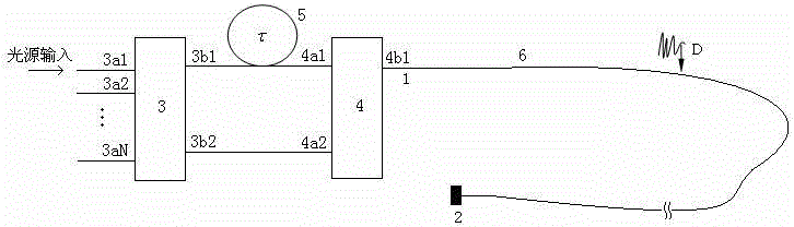
[0051] This embodiment adopts as figure 2 The interference structure is shown. The light source used is the SO3-B super-superluminant diode (SLD) produced by the 44 Research Institute of the Electronics Group Corporation, with a working wavelength of 1310nm. Coupler 3 uses a 3*3 optical fiber fused tapered single-mode coupler that is equally divided, and coupler 4 uses a 2*2 optical fiber fused tapered single-mode coupler that is equally divided, both of which are produced by Wuhan Institute of Posts and Telecommunications. The optical fiber used in the optical fiber delayer is G652 type single-mode optical fiber. The photoelectric conversion device used in photoelectric conversion and information processing is an InGaAs photodetector model GT322C500 produced by 44. The feedback device 2 is made of evaporated aluminum film at the end of the optical fiber, and the reflectivity is greater than 95%. The phase modulator 9 connected in series at the tail end is made by winding ...


PUM


Abstract

The invention belongs to the technical field of optical fiber sensing, in particular to a method for eliminating backscattering light influence in an optical fiber sensor. By arranging a phase modulator at the tail end of a sensing optical fiber (cable) and using modulation and demodulation technology for phase generated carrier, a useful interference signal is extracted from a signal interfered by optical fiber scattering light. The method can make a great breakthrough in monitoring distance of the traditional optical fiber sensing equipment, and the method also represents new application ofthe phase generated carrier technology.

Description

technical field [0001] The invention belongs to the technical field of optical fiber sensing, and in particular relates to a method for eliminating the influence of backscattered light in an optical fiber sensor. Background technique [0002] Optical fiber sensing technology is often used in large-scale and long-distance monitoring, such as in the safety monitoring of oil pipelines, high-voltage power grids, gas pipelines, communication optical cables and other infrastructures. It uses optical fibers as sensors to collect relevant information in real time. Disturbance signal, through the analysis of the characteristics to determine the location of the disturbance. The single-core feedback optical path structure uses a single optical fiber in the sensing section, and the optical fiber itself does not need to be closed. Only a feedback device, such as a mirror, is added at the end of the optical fiber to form an interference optical path. In practical application, this struct...

Claims


Application Information

Patent Timeline
Patent Type & Authority Patents(China)
IPC IPC(8): G01D3/028
Inventor 肖倩贾波
Owner FUDAN UNIV
Why Eureka
Try Eureka