Distributed optical fiber identification system and method for hydraulic structures and their basic seepage conditions

A technology of distributed optical fiber and hydraulic structure, which is applied in the direction of permeability/surface area analysis, testing of machine/structural components, testing of moving fluid/granular solid, etc. It can solve the problems of increasing the cost of producing optical fiber, complex coding, and voltage instability and other issues, to achieve the effect of improving engineering application capabilities, expanding the scope of application, and facilitating production and manufacturing

Active Publication Date: 2016-01-27
HOHAI UNIV
View PDF7 Cites 0 Cited by
  • Summary
  • Abstract
  • Description
  • Claims
  • Application Information

AI Technical Summary

Problems solved by technology

[0006] The distributed optical fiber temperature sensor with integrated optical fiber Raman amplifier only amplifies and improves the analog electrical signal, but it does not fundamentally solve the problems of pulse width and signal-to-noise ratio; the distributed optical fiber Raman temperature sensor using pulse encoding technology, It is mainly aimed at single-mode fiber, and in order to improve the signal-to-noise ratio of the system and the ability to extract and distinguish signals, complex encoding and decoding techniques are required, which greatly increases the difficulty of operation and the complexity of equipment design. From its final spatial resolution In terms of the signal-to-noise ratio of the system, there are still major deficiencies; the distributed optical fiber temperature sensor using Raman correlation dual-wavelength self-calibration technology, the use of dual light sources still cannot guarantee the temperature measurement of the two channels in the same band. With the same loss, the temperature demodulation curve will still have problems such as tilt and distortion; the distributed optical fiber temperature sensor embedded in the optical switch can expand the temperature measurement optical fiber from the original one to multiple by adding an optical switch, but its accuracy and Timeliness of measurement is difficult to guarantee
[0007] On the other hand, most of the current seepage monitoring technologies based on sensing optical fibers need to use external circuits to heat the optical fibers. Therefore, not only the optical fibers used are required to have a heating function, but also a complete heating circuit must be constructed, which greatly increases production. The cost of the optical fiber, and because it is difficult to coordinate the relationship between the voltage of the external circuit and the heating optical fiber during indoor and outdoor monitoring, the produced heating optical fiber often has voltage instability or excessive phenomenon in this case, and the Because of the difficult-to-control voltage, the fiber sheath will be soft or even burnt, which will cause extremely serious harm to operators and instruments; in addition, the on-site monitoring applied to actual projects often lacks necessary safety measures, and it is difficult to lay heating circuits. Especially for water conservancy and hydropower projects such as dams, because most of them are located in remote areas and the service environment is extremely harsh, the realization of optical fiber laying and heating functions is more difficult or even impossible

Method used


Image

  • Distributed optical fiber identification system and method for hydraulic structures and their basic seepage conditions
  • Distributed optical fiber identification system and method for hydraulic structures and their basic seepage conditions
  • Distributed optical fiber identification system and method for hydraulic structures and their basic seepage conditions

Examples


Embodiment Construction

[0034] The present invention will be further described below in conjunction with the accompanying drawings.

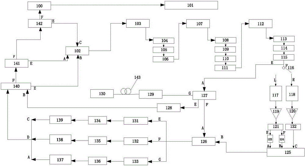
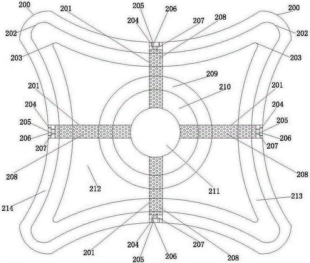
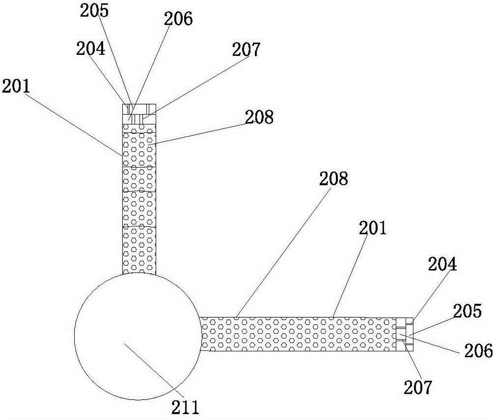
[0035] like Figure 1 to Figure 3 As shown in the figure, a distributed optical fiber identification system for a hydraulic structure and its basic seepage state of the present invention includes a special single-mode fiber 143 for self-controlled heat source seepage measurement that is vertically staggered in the seepage monitoring area 130 of the hydraulic structure, and The optical path coupler 127 and the synchronization controller 102 are connected with the special single-mode optical fiber 143 for self-controlling heat source osmotic measurement. The controller 102 communicates with the mode-locked laser 103, the first wavelength division multiplexer 104, the polarization beam splitter 105, the isolator 106, the nonlinear amplifier 107, the grating pair 108, the liquid crystal spatial light modulator 109, the diffraction grating 110, the reflection The mirror 11...


PUM


Abstract

The invention discloses a distributed optical fiber identification system and method for hydraulic structures and their foundation seepage conditions. The system includes a special single-mode optical fiber for self-controlled heat source seepage measurement, an optical path coupler and a synchronous controller, a synchronous controller and a mode-locked laser. , polarizing beam splitter, isolator, grating pair, diffraction grating, reflector, beam splitter, nonlinear crystal, spectrometer and Michelson interferometer are connected, the output end of Michelson interferometer is connected to the optical coupler, and the optical coupler The output ends are respectively connected with the detector and the second optical splitter, the detector is connected with the digital signal processor, the second optical splitter is connected with the digital signal processor through the amplification circuit, and the digital signal processor is respectively connected with the synchronous controller and the collector connect. The invention has the advantages of high precision, high spatial resolution, high sensing speed, long-distance monitoring, etc., and can realize process and automation of seepage monitoring and status identification of hydraulic structures and their foundations in harsh environments.

Description

technical field [0001] The invention relates to a hydraulic structure and a basic seepage monitoring system and method thereof, in particular to a distributed optical fiber identification system and method for a hydraulic structure and its basic seepage condition under harsh environment. Background technique [0002] Seepage is an important factor related to the safety and long-term service of hydraulic structures, especially for earth-rock dams, embankments and other soil-rock granular structures, the seepage problem and its influence are more prominent. To develop advanced, practical and reliable seepage measurement instruments and equipment for wading structures, strengthen their rational layout and efficient transmission and scientific processing and analysis of monitoring data, so as to accurately identify the seepage status of structures, is of great significance to ensuring project safety. With the rapid development of optical fiber sensing technology and the continuo...

Claims


Application Information

Patent Timeline
Patent Type & Authority Patents(China)
IPC IPC(8): G01N15/08
CPCG01K11/32G01M3/047G01K11/324G01K11/00B23P19/04G01N21/21G01N21/85G01N21/88
Inventor 苏怀智杨孟
Owner HOHAI UNIV
Why Eureka
Try Eureka