A pressure detection device and system

A detection device and pressure technology, applied in the field of measurement, can solve the problems of difficult disassembly, charging, maintenance and replacement of the detection device, limited measurement distance and working time, errors in ultrasonic echo measurement methods, etc., so as to improve reliability and service life. Simple structure, the effect of reducing structure and complexity

Active Publication Date: 2021-08-10
XIDIAN UNIV
View PDF18 Cites 0 Cited by
  • Summary
  • Abstract
  • Description
  • Claims
  • Application Information

AI Technical Summary

Problems solved by technology

[0004] However, this wired connection method makes the system structure of the pressure detection device larger, and is limited by the capacity of the wire and battery, and the distance it can measure and the working time are limited; and in practice, screws and nuts are often buried inside the building, thus As a result, it is difficult to disassemble, recharge, repair and replace the detection device; at the same time, the measurement method of ultrasonic echo is prone to errors caused by environmental influences, which affects the accuracy of measurement

Method used


Image

  • A pressure detection device and system
  • A pressure detection device and system
  • A pressure detection device and system

Examples


Embodiment 1

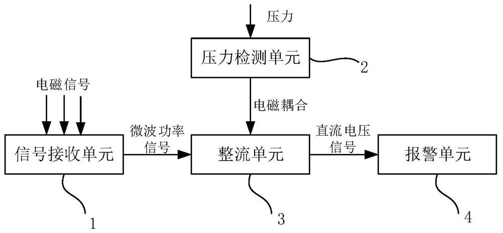
[0039] See figure 1 , figure 1 It is a schematic diagram of a pressure detection device provided by an embodiment of the present invention, including:

[0040] A signal receiving unit 1, configured to receive an electromagnetic signal, and convert the electromagnetic signal into a microwave power signal with a standard impedance;

[0041] A pressure detection unit 2, which has a pressure sensitive element, so that when the pressure detection unit 2 is subjected to the pressure applied by the object to be detected, the dielectric constant of the pressure sensitive element is changed;

[0042] The rectification unit 3 is connected to the pressure detection unit 1 through electromagnetic coupling, and is electrically connected to the signal receiving unit, and is used to rectify the microwave power signal and output a DC voltage signal, and the dielectric constant of the pressure sensitive element adjusting said DC voltage signal when a change occurs;

[0043] The alarm unit 4...

Embodiment 2

[0068] This embodiment provides a pressure detection system for detecting the pressure inside a building. See Figure 5 , Figure 5 It is a structural schematic diagram of a pressure detection system provided by an example of the present invention, including: a transmitting end A and a receiving end B, wherein,

[0069] The transmitting terminal A is used to transmit electromagnetic signals; it includes a signal source, an amplifier and a transmitting antenna;

[0070] The receiving terminal B is wirelessly connected to the transmitting terminal A, and is used to receive the electromagnetic signal and convert it into microwave power with standard impedance, and then rectify it into DC power, so as to output a voltage signal, which includes as in the first embodiment The pressure detection device.

[0071] Considering that the pressure detection system provided in this embodiment is used to detect the internal pressure of the building, the alarm device and the receiving end ...


PUM


Abstract

The invention discloses a pressure detection device, comprising: a signal receiving unit for receiving an electromagnetic signal and converting the electromagnetic signal into a microwave power signal with standard impedance; a pressure detection unit with a pressure sensitive element for When the pressure detection unit is subjected to the pressure exerted by the object to be detected, the dielectric constant of the pressure sensitive element is changed; the rectification unit is connected to the pressure detection unit through electromagnetic coupling, and is electrically connected to the signal receiving unit for The microwave power signal is rectified and a DC voltage signal is output, and the DC voltage signal is adjusted when the dielectric constant of the pressure-sensitive element changes; an alarm unit is connected to the rectification unit for The alarm is driven by the signal. The pressure detection device provided by the present invention realizes the signal connection between the pressure detection unit and the rectification unit by means of electromagnetic coupling to realize accurate pressure monitoring, reduces the system structure, improves the efficiency, and thus increases the measurement distance.

Description

technical field [0001] The invention belongs to the technical field of measurement, and in particular relates to a pressure detection device and system. Background technique [0002] A pressure sensor is a device or device that can sense pressure signals and convert the pressure signals into usable output electrical signals according to certain rules. As a commonly used sensor, it is widely used in various industrial automatic control environments, including Water conservancy and hydropower, railway transportation, intelligent buildings, production automation, aerospace and other fields. In engineering, in order to monitor the reliability of infrastructure structures such as bridges and buildings, it is often necessary to measure the pressure at stress points or screws and nuts. [0003] At present, the commonly used pressure detection devices use traditional wired sensors, that is, the sensor and the measurement circuit are connected by wires. After the sensor is pressed, ...

Claims


Application Information

Patent Timeline
Patent Type & Authority Patents(China)
IPC IPC(8): G01L1/14
CPCG01L1/144
Inventor 李杨杨嘉怡敖金平
Owner XIDIAN UNIV
Why Eureka
Try Eureka