Automatic pipe machining machine

A technology of automatic processing and pipe fittings, which is applied in the direction of metal processing machinery parts, metal processing, metal processing equipment, etc., can solve the problems that cannot meet the actual requirements, the length of pipe fittings is different, and the efficiency is not high.

Inactive Publication Date: 2011-04-13
旭东机械(昆山)有限公司
View PDF0 Cites 51 Cited by
  • Summary
  • Abstract
  • Description
  • Claims
  • Application Information

AI Technical Summary

Problems solved by technology

[0002] In the prior art, it is often necessary to chamfer the nozzle of the pipe fitting, expand the nozzle and punch the side of the nozzle at the same time. Such an operation requires many steps to complete, and requires multiple personnel to use multiple equipment to carry out , very cumbersome; because each operation process requires manual intervention, the efficiency is not high, and there are still potential safety hazards
In addition, if you want to process in large quantities, if the lengths of the pipe fittings in each batch are different, you need to cooperate with the cutting operation, so it cannot meet the actual requirements.

Method used


Image

  • Automatic pipe machining machine
  • Automatic pipe machining machine
  • Automatic pipe machining machine

Examples


Embodiment Construction

[0053]In conjunction with the accompanying drawings, the following is further described:

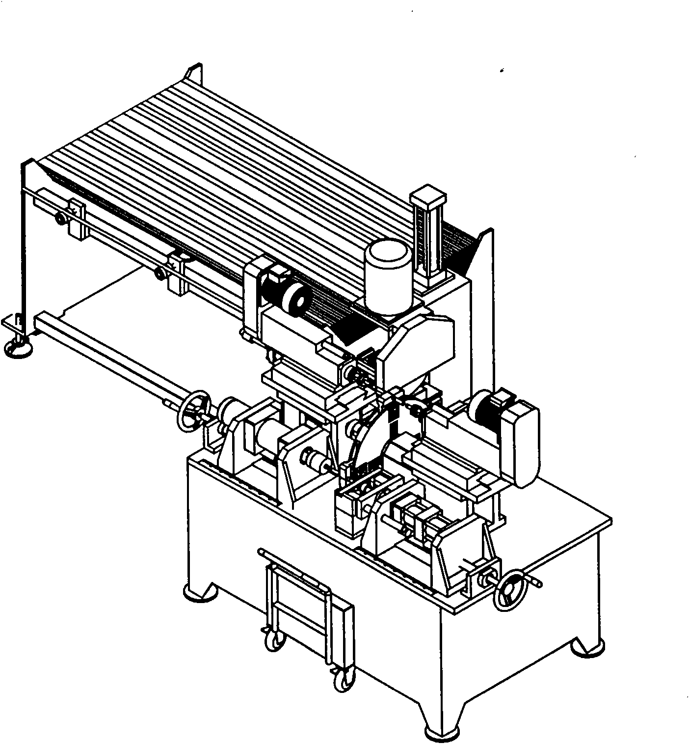
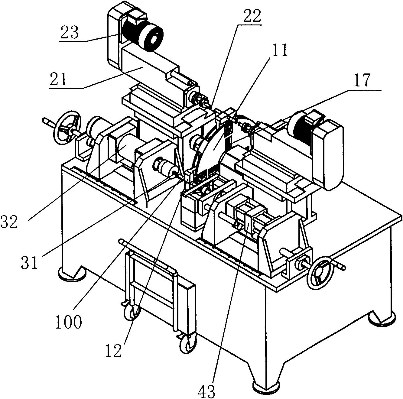
[0054] An automatic processing machine for pipe fittings, characterized in that it includes a transposition device capable of clamping pipe fittings and realizing transposition, and chamfering devices, pipe expanding and punching devices respectively located at the periphery of the transposition mechanism, wherein:

[0055] 1) The transposition device (such as figure 2 , Figure 4 As shown), it includes a rotating disk 11 and a servo motor that drives the rotating disk to rotate and shift. Four clamping mechanisms for clamping pipes are uniformly arranged on the circumference of the rotating disk. When three of the clamping mechanisms correspond to the For the cutting device, chamfering device and pipe expanding and punching device, another clamping mechanism corresponds to the pipe outlet, each clamping mechanism has a pair of clamping jaws 12, and a telescopic rod 13 that drives the ...


PUM


Abstract

The invention relates to an automatic pipe machining machine which comprises an interchanging device, a chamfering device and a pipe expanding and punching device, wherein the interchanging device comprises a rotating disk and a servo motor for driving the rotating disk to rotate and interchange, the periphery of the rotating disk is provided with a plurality of clamping mechanisms used for clamping pipes; the chamfering device comprises a rose reamer and a chamfering motor, wherein the rose reamer passes through a drilling spindle head and is fixed on the drilling spindle head, the chamfering motor is used for driving the drilling spindle head to drive the rose reamer to rotate; the pipe expanding and punching device comprises a pipe expanding mechanism and a punching mechanism which are respectively arranged at two sides of the rotating disk, the pipe expanding mechanism comprises a pipe expanding mould and a pipe expanding cylinder for driving the pipe expanding mould to expand a pipe mouth, the punching mechanism comprises a puncturing mould, a pair of fixing blocks with punching needles, and a double-stroke cylinder, the puncturing mould is fixed on a center cylinder rod of the double-stroke cylinder and driven by the center cylinder rod to be positioned at the pipe mouth, and the two fixing blocks are respectively used for driving the two punching needles and arranged at two sides of the puncturing mould side by side as well as driven by an external cylinder rod on the double-stroke cylinder to slide along the direction vertical to the pipes.

Description

technical field [0001] The invention relates to pipe fitting processing equipment, in particular to an automatic processing machine capable of chamfering, pipe expanding, punching and other operations on pipe fittings at the same time. Background technique [0002] In the prior art, it is often necessary to chamfer the nozzle of the pipe fitting, expand the nozzle and punch the side of the nozzle at the same time. Such an operation requires many steps to complete, and requires multiple personnel to use multiple equipment to carry out , very cumbersome; because each operation process requires manual intervention, the efficiency is not high, and potential safety hazards still exist. In addition, if large batches of processing are to be processed, if the lengths of pipe fittings of each batch are different, the cooperation of cutting operation is also required, so the actual requirements cannot be met. Contents of the invention [0003] In order to make up for the above shor...

Claims


Application Information

Patent Timeline
Patent Type & Authority Applications(China)
IPC IPC(8): B23P23/00B23Q16/02B23Q3/06B23C3/12B21D41/02B21D28/28B23D45/12B23D47/04B23D47/12B23Q7/06B23Q7/04
Inventor 刘家真丁雷敏张凯
Owner 旭东机械(昆山)有限公司
Why Eureka
Try Eureka