Continuous lead-smelting device and continuous lead-smelting process

A lead smelting and process technology, applied in lighting and heating equipment and other directions, can solve the problems of high cost, high energy consumption, and difficult to control the lead content of the final slag, and achieve the effects of good sealing performance, high environmental protection, and reduced energy consumption.

Active Publication Date: 2011-04-13
CHINA ENFI ENGINEERING CORPORATION
View PDF3 Cites 23 Cited by
  • Summary
  • Abstract
  • Description
  • Claims
  • Application Information

AI Technical Summary

Problems solved by technology

However, the dust rate of the QSL method is as high as 25-30%, and due to the use of bottom blowing, the part of the reduced crude lead is repeatedly oxidized and reduced, and the lead content in the fi

Method used


Image

  • Continuous lead-smelting device and continuous lead-smelting process
  • Continuous lead-smelting device and continuous lead-smelting process
  • Continuous lead-smelting device and continuous lead-smelting process

Examples


Embodiment Construction

[0035] Embodiments of the present invention are described in detail below, examples of which are shown in the drawings, wherein the same or similar reference numerals designate the same or similar elements or elements having the same or similar functions throughout. The embodiments described below by referring to the figures are exemplary only for explaining the present invention and should not be construed as limiting the present invention.

[0036] In the description of the present invention, the terms "longitudinal", "transverse", "upper", "lower", "front", "rear", "left", "right", "vertical", "horizontal", " The orientations or positional relationships indicated by "top", "bottom", etc. are based on the orientations or positional relationships shown in the drawings, and are only for the convenience of describing the present invention and do not require that the present invention must be constructed and operated in a specific orientation, so they cannot be understood as Lim...


PUM


Abstract

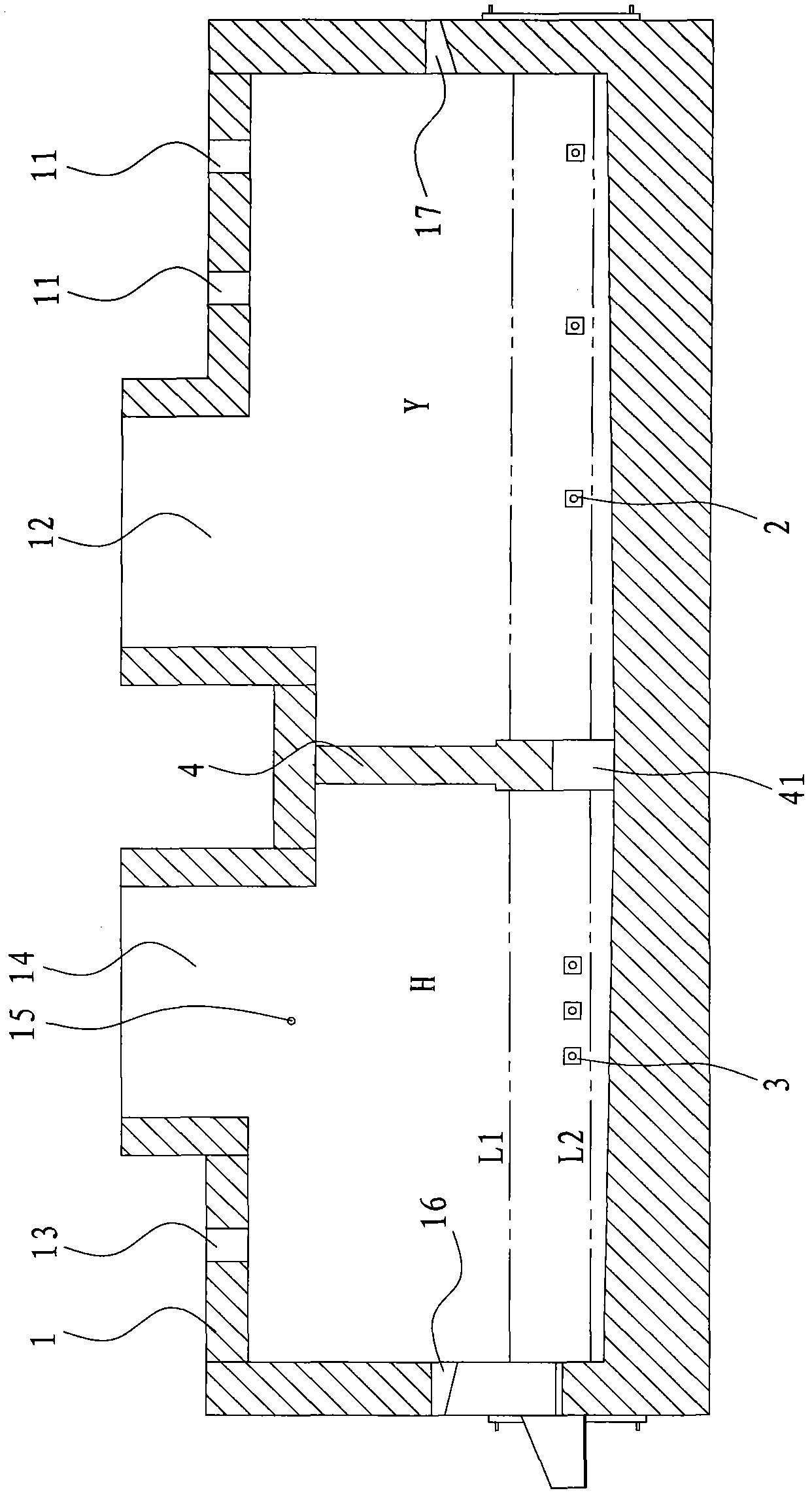
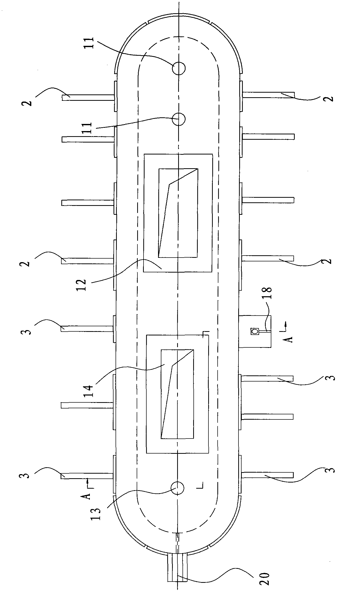
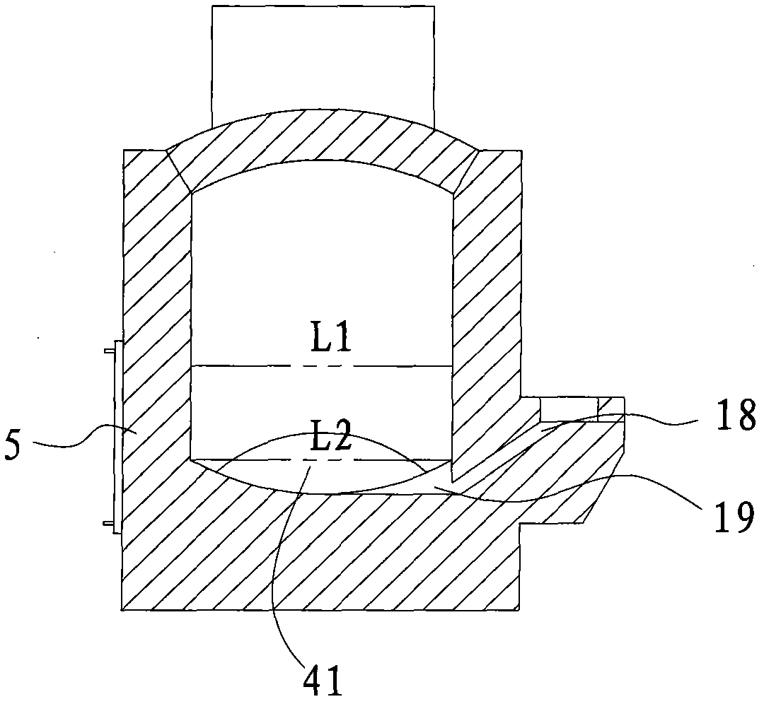
The invention discloses a continuous lead-smelting device which comprises a reaction furnace, a side-blown spraying gun for an oxidation zone and a side-blown spraying gun for a reduction zone, wherein, the reaction furnace is internally equipped with a partition wall for dividing a furnace chamber of the reaction furnace into the oxidation zone and the reduction zone, the lower part of the furnace chamber forms a molten pool, the bottom of the partition wall is equipped with a communicating channel for communicating the oxidation zone with the reduction zone, the roof of the oxidation zone is respectively equipped with a feed inlet for the oxidation zone and a flue gas outlet for the oxidation zone respectively, the roof of the reduction zone is equipped with a reductant feed inlet and a flue gas outlet for the reduction zone, and the furnace wall of the furnace chamber is equipped with a siphon lead discharge port and a slag discharge port; the side-blown spraying gun for the oxidation zone is connected with the side wall of the oxidation zone of the reaction furnace so as to laterally blow oxygen into the molten pool of the oxidation zone; and the side-blown spraying gun for the reduction zone is connected with the side wall of the reduction zone of the reaction furnace so as to laterally blow fuel and oxygen into the reduction zone. The continuous lead-smelting device disclosed by the invention has the advantages that oxidation and reduction are realized in single reaction furnace, lead content in slag is low, stability and tightness are good, environmental protection property is high, heat content of the slag is fully utilized and energy consumption is lowered. The invention further provides a continuous lead-smelting process.

Description

technical field [0001] The invention relates to a lead smelting device and process, in particular to a continuous lead smelting device and a continuous lead smelting process. Background technique [0002] In recent years, in order to improve the environment, the lead smelting processes that have been used in industrial production at home and abroad mainly include QSL method, SKS method, Kivcet method, and top blowing submerged molten pool smelting technology (mainly Ausmelt method, ISA method and Caldo method). The Kaldor lead smelting method is difficult to popularize and apply due to short furnace life, low operation rate and high cost. The SKS method, the ISA-blast furnace reduction lead smelting method is a method of redox smelting in two separate furnaces, the Ausmelt method is a method of redox in a single furnace, and the QSL method and Kivcet method are in The redox process is realized in different regions in a single furnace. However, the Ausmelt method has a high...

Claims


Application Information

Patent Timeline
IPC IPC(8): C22B13/02
CPCF27B3/045C22B13/02C22C1/02
Inventor 陆志方王忠实伍绍辉李东波黄祥华朱让贤姚霞吴卫国林屹
Owner CHINA ENFI ENGINEERING CORPORATION
Why Eureka
Try Eureka