Pressure reducing valve and use thereof as well as fluid conveying system

A technology of fluid conveying system and pressure reducing valve, which is applied in the direction of conveyors, conveying bulk materials, balance valves, etc. It can solve the problems of uncomfortable pressure reduction adjustment, easy wear and blockage of flow channels, etc., and achieves the effect of easy maintenance and simple structure

Active Publication Date: 2011-04-13
CHNA ENERGY INVESTMENT CORP LTD +1
View PDF7 Cites 6 Cited by
  • Summary
  • Abstract
  • Description
  • Claims
  • Application Information

AI Technical Summary

Problems solved by technology

However, this structure is suitable for the decompression adjustment of gas or liquid in clean media. For materials with high solid content, the tortuous flow path is easy to wear and block, and it is not suitable for materials with high temperature and high pressure difference and high solid content. decompression regulation

Method used


Image

  • Pressure reducing valve and use thereof as well as fluid conveying system
  • Pressure reducing valve and use thereof as well as fluid conveying system
  • Pressure reducing valve and use thereof as well as fluid conveying system

Examples


Embodiment 1

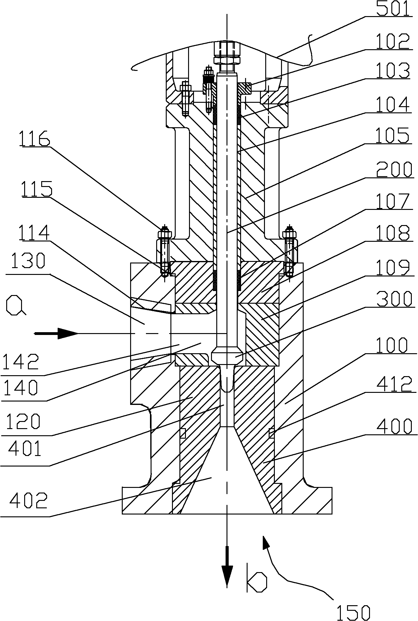
[0116] In the direct coal liquefaction process, the coal slurry reacted in the reactor is transported to the high-temperature and high-pressure separator, the medium temperature is 450°C, and the pressure is 19MPa. Its pressure is reduced to 3MPa through a pressure reducing valve and enters a medium-temperature and medium-pressure separator. The flow rate of coal slurry is 360L / h, and the system requires the liquid level of the high temperature and high pressure separator to be kept stable.

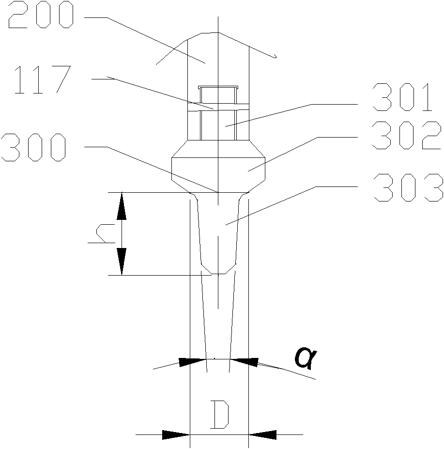
[0117] The valve stem drives the valve core connected with it to move up and down, and the opening of the valve core is controlled at 25%-40%, and the gap between the valve core and the valve seat is adjusted, that is, the flow rate of the coal slurry is adjusted to 300-400L / h , to ensure a relatively stable liquid level in the high-temperature and high-pressure separator, and at the same time realize decompression to reduce the pressure to 3MPa.

Embodiment 2

[0119] In the direct coal liquefaction process, the coal slurry reacted in the reactor is transported to the high-temperature and high-pressure separator, the medium temperature is 450°C, and the pressure is 19MPa. Its pressure is reduced to 1MPa through the pressure reducing valve and enters the storage tank. The flow rate of coal slurry is 400L / h, and the system requires the liquid level of the high temperature and high pressure separator to be kept stable.

[0120] The valve stem drives the valve core connected with it to move up and down, and the opening of the valve core is controlled at 25%-30%, and the gap between the valve core and the valve seat is adjusted, that is, the flow rate of the coal slurry is adjusted to 380-420L / h , to ensure a relatively stable liquid level in the high-temperature and high-pressure separator, and at the same time realize decompression to reduce the pressure to 1MPa.


PUM


Abstract

The invention relates to a pressure reducing valve and use thereof as well as a fluid conveying system. The pressure reducing valve comprises a valve body, a valve cavity, a valve rod and a valve element, wherein, the valve body is provided with a lateral inlet and a lower outlet; the lateral inlet, the valve cavity and an outlet channel form a fluid channel; the valve rod extends in the valve body and can move along the longitudinal axis of the valve rod, and the valve rod is provided with a first end and a second end; the valve element is provided with a valve element connecting part which is positioned on the upper end of the valve element and is fixedly connected or bonded with the first end of the valve rod, a valve element middle part and a valve head positioned on the lower end of the valve element; the diameter D1 of the valve element middle part is more than the diameter d1 of the outlet channel; and at least one part of the valve head can be accommodated in the outlet channel and can move along the longitudinal axis direction of the outlet channel. The pressure reducing valve has the advantages of simple structure and applicability to a high solid content material decompression and control system, and is easy to maintain.

Description

technical field [0001] The invention relates to a pressure reducing valve, its application, and a fluid conveying system. Background technique [0002] The pressure reducing valve is a pressure control valve. When the pressure of the hydraulic system reaches the set value of the valve, the pressure reducing valve discharges part or all of the liquid, reducing the inlet pressure to a certain required pressure, so as to realize the pressure reduction in the hydraulic system. Function to keep the pressure below the set value. From the point of view of fluid mechanics, the pressure reducing valve is a throttling element whose local resistance can be changed, that is, by changing the throttling area, the flow velocity and kinetic energy are changed, resulting in different pressure losses, so as to achieve the purpose of decompression, and then rely on control With the adjustment of the regulating system, the pressure after the valve is kept constant within a certain error range....

Claims


Application Information

Patent Timeline
Patent Type & Authority Applications(China)
IPC IPC(8): F16K17/00B65G53/46B65G53/00
Inventor 赵振秋舒歌平宋志平张继明章序文谢瞬敏赵宏世安亮韩来喜王建立
Owner CHNA ENERGY INVESTMENT CORP LTD
Why Eureka
Try Eureka