
LED (light emitting diode) lighting module

A LED lighting and superconducting technology, applied in energy-saving lighting, lighting devices, fixed lighting devices, etc., can solve the problems of slow heat dissipation of substrate temperature, complex heat dissipation links, small light angle, etc., to prolong working life, improve luminous efficiency, Effect of reducing operating temperature rise

Inactive Publication Date: 2011-04-13
王春
View PDF0 Cites 2 Cited by
  • Summary
  • Abstract
  • Description
  • Claims
  • Application Information

AI Technical Summary

Problems solved by technology

[0002] At present, the high-power LED lighting module has the following deficiencies: (1) the substrate of multiple LED chip packages is small, the heat dissipation link is complicated, and the temperature of the substrate is slow to dissipate heat, which greatly affects the normal operation of the LED chip; (2) when the LED chip emits light, the photon Due to the large reflection loss caused by the difference in refractive index at the exit interface, the light extraction efficiency is reduced; (3) when multiple LED chips are packaged, because the bracket blocks part of the light, the angle of the LED chip when it emits light becomes smaller; (4) LED After the light source is matched with the heat sink and the lamp housing, the structure is complex, the cost is high, and the effect is poor; Disadvantages such as poor light color quality

Method used


Image

  • LED (light emitting diode) lighting module
  • LED (light emitting diode) lighting module
  • LED (light emitting diode) lighting module

Examples


Embodiment Construction

[0022] The technical solution of the present invention will be described in detail below in conjunction with the accompanying drawings.

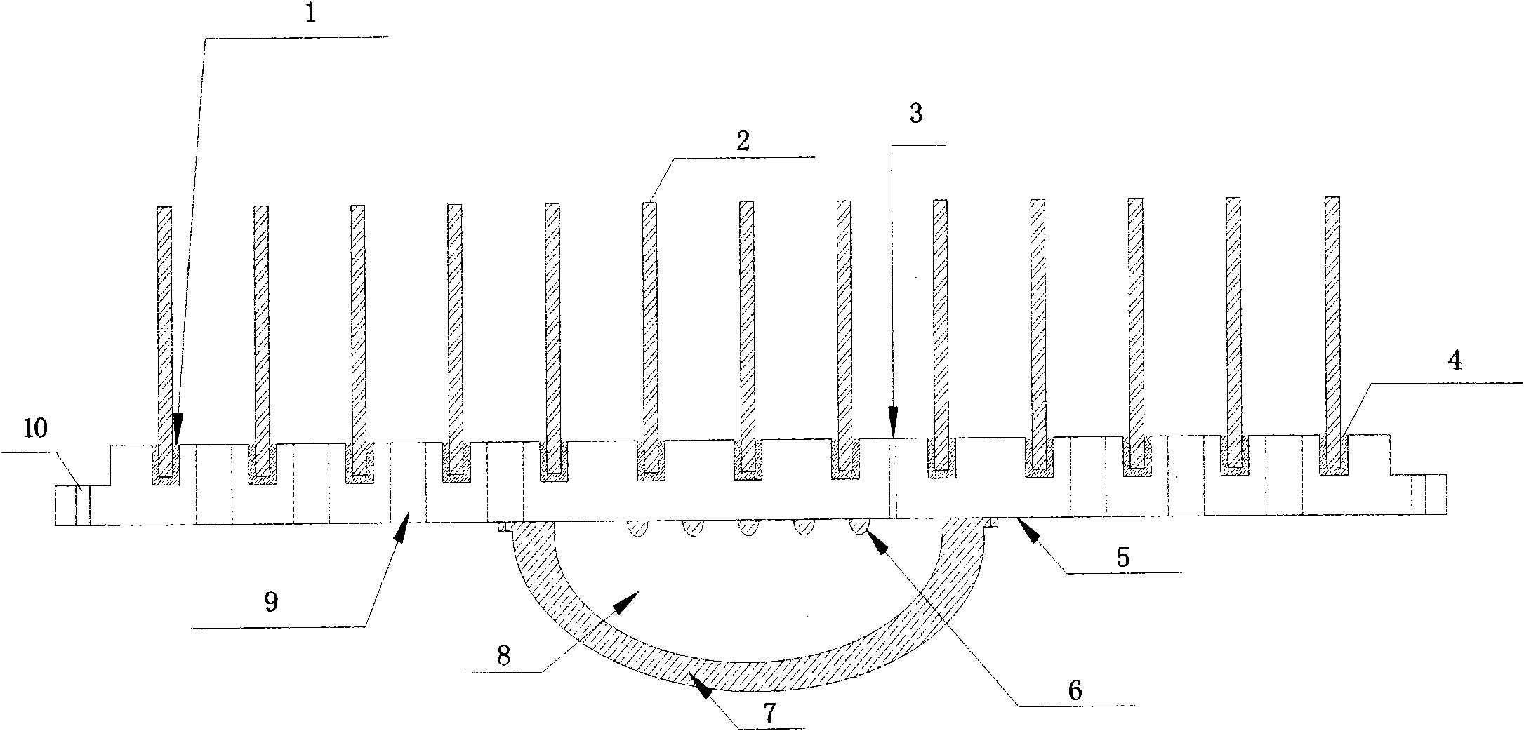
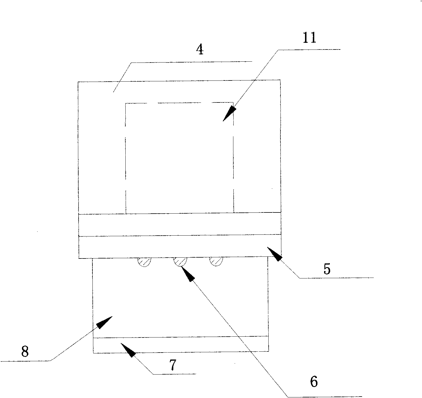
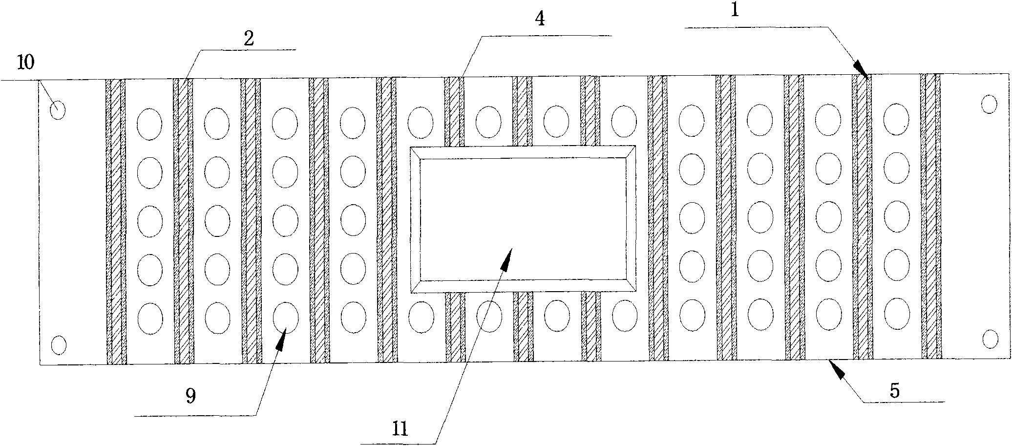
[0023] The LED lighting module includes a ceramic heat sink, a power supply box, a superconducting base and a light source room. The LED lighting module is provided with a plurality of connecting grooves for ceramic heat sinks on the superconducting base with a plurality of upper and lower transparent heat dissipation holes, and the superconducting base of the ceramic heat sink cavity is formed as a whole through an epoxy resin heat conducting layer, At the same time, a power supply box for installing a driving power supply is provided on the superconducting base; a plurality of LED chips are arrayed at the bottom of the superconducting base, and the LED chips are covered by a light distribution lens to form a light source chamber. The inventive light source room and power supply box of the invention are in a separated state, and the heat si...


PUM


Abstract

The invention relates to the field of modular LED (light emitting diode) street lamp lighting, in particular to an LED lighting module which is composed of ceramic radiating fins, a power box, a superconductive base and a light source chamber, wherein a plurality of ceramic radiating fin connecting grooves are arranged on the superconductive base with a plurality of vertically thorough heat dissipation holes, the ceramic radiating fin cavity forms into an whole through an epoxy resin heat conducting layer, and meanwhile, the power box, in which a driving power supply is arranged, is arranged on the superconductive base; and a plurality of LED wafers are arrayed on the bottom part of the superconductive base, and the LED wafers are covered by a light distribution lens to form the light source chamber. Therefore, the light source chamber and power box of the LED lighting module are separated, a radiator and a lamp cover are designed integrally, so that the radiating links are reduced, the heat conduction and heat dissipation performances are improved greatly, and the LED lighting module has the characteristics of improved luminous efficiency, prolonged service life, compact structure, low cost, and the like.

Description

technical field [0001] The invention relates to an LED lighting module, which is mainly used in high-power LED road lighting and belongs to the integrated application field of high-power LED light sources. Background technique [0002] At present, the high-power LED lighting module has the following deficiencies: (1) the substrate of multiple LED chip packages is small, the heat dissipation link is complicated, and the temperature of the substrate is slow to dissipate heat, which greatly affects the normal operation of the LED chip; (2) when the LED chip emits light, the photon Due to the large reflection loss caused by the difference in refractive index at the exit interface, the light extraction efficiency is reduced; (3) when multiple LED chips are packaged, because the bracket blocks part of the light, the angle of the LED chip when it emits light becomes smaller; (4) LED After the light source is matched with the heat sink and the lamp housing, the structure is complex,...

Claims


Application Information

Patent Timeline
Patent Type & Authority Applications(China)
IPC IPC(8): F21S4/00F21V29/00F21Y101/02F21S8/00F21V29/508F21V29/71F21Y115/10
CPCY02B20/72
Inventor 王春
Owner 王春
Learn More