Self-cleaning heat exchanger

A technology for automatic cleaning and heat exchangers, which is applied to heat exchange equipment, heat exchanger types, heat exchanger shells, etc., and can solve the problems of heat exchange efficiency decline, high labor intensity, and fouling on the surface of heat transfer tubes, etc. problems, to achieve the effect of maintaining heat exchange efficiency, ensuring normal operation, and avoiding manual labor

Inactive Publication Date: 2015-06-24
FUJIAN NEWLAND ENTECH CO LTD
View PDF7 Cites 0 Cited by
  • Summary
  • Abstract
  • Description
  • Claims
  • Application Information

AI Technical Summary

Problems solved by technology

[0002] At present, industrial water-cooled heat exchangers are widely used in pharmaceutical factories, power plants and other fields. With the passage of time, the surface of the heat transfer tube will inevitably be eroded by the medium, resulting in scaling and erosion on the surface of the heat transfer tube. The phenomenon is serious, causing the heat exchange efficiency of the heat exchanger to drop sharply, seriously affecting the normal operation of the system
In the current heat exchanger, the inner surface of the heat transfer tube is cleaned more, and the equipment for cleaning the outer surface of the heat transfer tube is rare. Since the heat transfer tube is densely arranged in the heat exchanger, the external The cleaning of the surface is not easy to achieve. If it is cleaned manually, the cleaning efficiency is low, the labor intensity is high, and the cost is high. If it is cleaned chemically, the chemical substance will pollute the steam or cooling medium that needs to be condensed. Generally, it is not recommended to use it.
And if it is necessary to clean with the above method, the system needs to be shut down, which will affect the normal production

Method used


Image

  • Self-cleaning heat exchanger
  • Self-cleaning heat exchanger

Examples


Embodiment Construction

[0019] An embodiment of the present invention will be specifically described below in conjunction with the accompanying drawings.

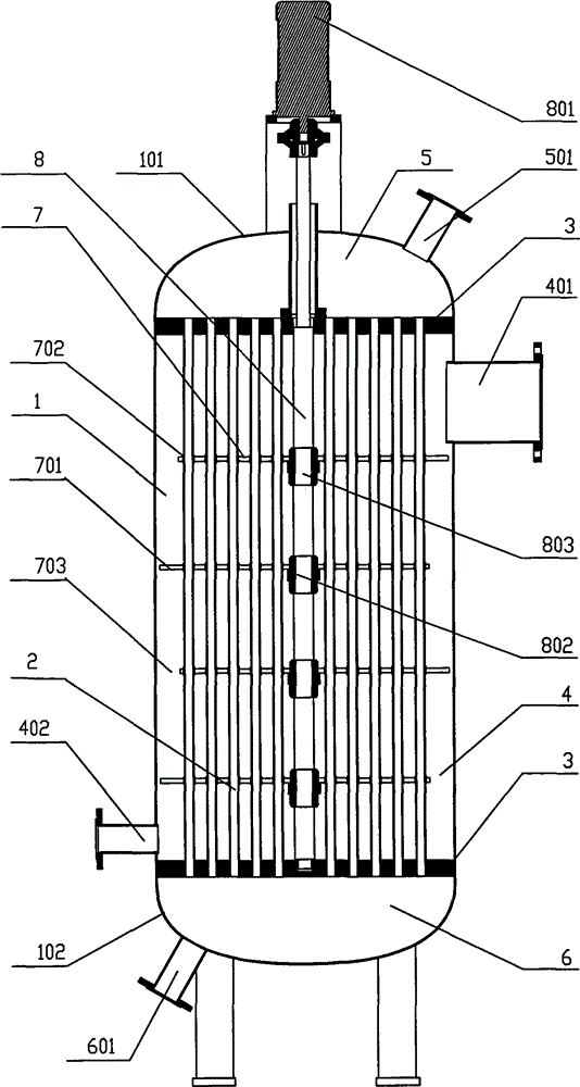
[0020] Such as figure 1 , 2 As shown in , the self-cleaning heat exchanger provided by the present invention includes a cylinder body 1 with end caps at both ends and a set of heat transfer tubes 2 parallel to each other, and also includes an automatic cleaning device 7, the medium The inlet 401 and outlet 402 of A are respectively arranged on the two ends of the cylinder wall, the heat transfer tube 2 is a straight tube, and its two ends are respectively fixed on a mounting plate 3, and the two mounting plates 3 and A heat exchange chamber 4 is formed between the cylinder walls; the two ends of the heat exchange chamber 4 are provided with a medium A inlet 401 and a medium A outlet 402; When installing the heat transfer tube 2, a medium B outlet buffer chamber 5 is formed between one of the mounting plates 3 and the outer first end cover 101 of...


PUM


Abstract

The invention provides a self-cleaning heat exchanger. The heat exchanger comprises a cylinder body, a set of mutually-parallel heat transfer tubes, and an automatic cleaning device, wherein the two ends of the cylinder body are respectively provided with an end cover, and a medium A inlet and a medium A outlet are respectively arranged at the two ends of the cylinder body wall; the heat transfer tube is a straight tube, the two end parts of the heat transfer tube are respectively fixed on a mounting plate, and a heat transfer cavity is formed between each of the two mounting plates and the cylinder body wall; a medium B inlet cushion cavity is formed between one of the two mounting plates and the end cover of the cylinder at the outer side of the one mounting plate; a medium B outlet cushion cavity is formed between the other mounting plate and the end cover of the cylinder at the outer side of the other mounting plate; and the automatic cleaning device comprises a cleaning frame, a scrubbing annular sheet and a driving device, and the cleaning device is driven to carry out reciprocating motion along the axial direction of the heat transfer tubes by the driving device. The heat exchanger of the invention can be widely applied to the industries requiring for refrigeration, such as the cooling systems of pharmaceutical factories, power plants and boilers, etc.

Description

Technical field: [0001] The invention relates to an automatic cleaning heat exchanger, which belongs to the field of heat exchangers. Background technique: [0002] At present, industrial water-cooled heat exchangers are widely used in pharmaceutical factories, power plants and other fields. With the passage of time, the surface of the heat transfer tube will inevitably be eroded by the medium, resulting in scaling and erosion on the surface of the heat transfer tube. The phenomenon is serious, causing the heat exchange efficiency of the heat exchanger to drop sharply, seriously affecting the normal operation of the system. In the current heat exchanger, the inner surface of the heat transfer tube is cleaned more, and the equipment for cleaning the outer surface of the heat transfer tube is rare. Since the heat transfer tube is densely arranged in the heat exchanger, the external Surface cleaning is not easy to achieve. If manual cleaning is used, the cleaning efficiency is...

Claims


Application Information

Patent Timeline
Patent Type & Authority Patents(China)
IPC IPC(8): F28D7/10F28F9/22F28G1/00
Inventor 陈健李永熙
Owner FUJIAN NEWLAND ENTECH CO LTD
Why Eureka
Try Eureka