Electromagnetic forming device and method for micro fuel cell metal bipolar plate microchannel

A technology of micro-fuel cells and metal bipolar plates, which is applied to battery electrodes, circuits, electrical components, etc., can solve problems such as difficulty in matching between micro-convex and concave dies, shorten processing time, reduce processing costs, and be easy to replace Effect

Active Publication Date: 2011-04-13
HARBIN INST OF TECH
View PDF2 Cites 35 Cited by
  • Summary
  • Abstract
  • Description
  • Claims
  • Application Information

AI Technical Summary

Problems solved by technology

[0004] The object of the present invention is to provide a kind of electromagnetic forming device and method of the micro-channel of the metal bipolar plate of the micro-fuel cell, to solve the gap be

Method used


Image

  • Electromagnetic forming device and method for micro fuel cell metal bipolar plate microchannel
  • Electromagnetic forming device and method for micro fuel cell metal bipolar plate microchannel
  • Electromagnetic forming device and method for micro fuel cell metal bipolar plate microchannel

Examples


specific Embodiment approach 1

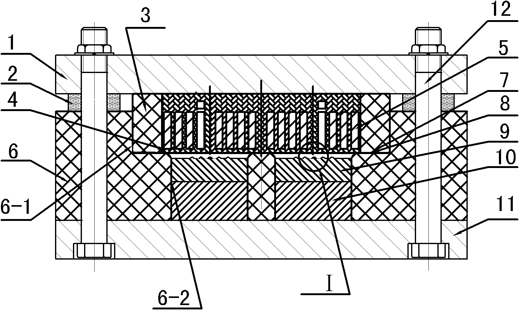
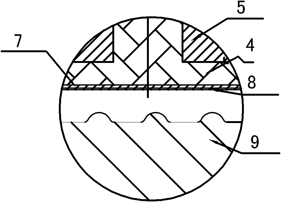
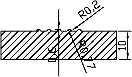
[0009] Specific implementation mode one: the following combination figure 1 and figure 2 This embodiment will be specifically described. The electromagnetic forming device of the micro-channel of the metal bipolar plate of the micro-fuel cell of the present embodiment includes an upper template 1, a backing ring 2, a coil frame 3, a potting material 4, a coil 5, a support frame 6, a driving piece 7, and a mold 9. Spacer 10, lower formwork 11 and coil frame 12. The support frame 6 is arranged on the upper surface of the lower formwork 11. There is a groove 6-1 on the upper surface of the support frame 6 to place the coil 5. At the bottom center of the groove 6-1 There is a circular through hole 6-2 to place the mold 9 and the pad 10, the mold 9 and the pad 10 are stacked up and down, and the distance between the mold 9 and the bottom of the groove is regulated by the pad 10. The bottom of the groove 6-1 and the top of the mold 9 are the drive pieces 7, the coil frame 3, the ...

specific Embodiment approach 2

[0012] Specific implementation mode two: the following combination figure 1 This embodiment will be specifically described. The difference between this embodiment and Embodiment 1 is that it also includes a backing ring 2, and each bolt 12 is provided with a backing ring 2, and the backing ring 2 is arranged between the upper template 1 and the support frame 6, and the backing ring 2 is divided into two parts. There are two kinds of spacer rings and shock-absorbing spacer rings, the spacer spacer ring is made of metal, and the shock-absorbing spacer ring is made of polyurethane material. There is a backing ring 2 that cooperates with bolts above the support frame 6, and the upper formwork is above the backing ring. The fastening force between the support frame 6 and the upper template 1 is realized by bolts 12 . In this embodiment, six backing rings are used in conjunction with six bolts 12, two metal backing rings are used for positioning, and four polyurethane backing ring...

specific Embodiment approach 3

[0013] Specific implementation mode three: the following combination figure 1 This embodiment will be specifically described. The difference between this embodiment and the first embodiment is that epoxy resin, polyamide and insulating materials that can provide electrical insulation and mechanical support are used in the gap between the bobbin 3 and the coil 5 and in the gap between the pitches of the coil 5 . Metal oxide hybrid potting.


PUM

PropertyMeasurementUnit
Thicknessaaaaaaaaaa
Outer diameteraaaaaaaaaa
The inside diameter ofaaaaaaaaaa

Abstract

The invention discloses an electromagnetic forming device and an electromagnetic forming method for a micro fuel cell metal bipolar plate microchannel, and relates to a micro fuel cell metal bipolar plate microchannel forming device and a micro fuel cell metal bipolar plate microchannel forming method so as to solve the problem of matching difficulty between micro male and female dies in the process of forming a microstructure on a metal thin plate based on stamping and other conventional plastic deformation means. The device comprises an upper template, a coil, a driving sheet, a die, a lower template and a fastening bolt; a groove is formed on the surface of a supporting frame so as to accommodate the coil; a circular through hole is formed in the center of the bottom of the groove so as to accommodate the die; the driving sheet is arranged above the die; and an axial lead of the coil is in upper and lower directions. The method comprises the following steps of: discharging to the coil to excite a strong pulsed magnetic field; generating induced eddy on the surface of the driving sheet so as to generate a magnetic field opposite to the magnetic field of the coil in the transient strong pulsed magnetic field; and driving a plate blank to make die attaching motion by using the driving sheet under repellent applied force between the magnetic fields. The invention is used for micro-forming.

Description

technical field [0001] The invention relates to a forming device for the micro channel structure of the metal bipolar plate of the micro fuel cell, and also relates to a forming method for the micro channel structure of the metal bipolar plate of the micro fuel cell. Background technique [0002] Proton exchange membrane fuel cell is one of the main development directions of micro fuel cell. However, the miniaturization of fuel cell makes it more difficult to manufacture key components such as flow field plate. The membrane electrode (MEA) composed of electrolyte membrane, catalytic layer and gas diffusion layer is the core of the fuel cell, and the bipolar plate flow field plate is one of the key components of the fuel cell. The flow field plate is used in the micro-proton exchange membrane fuel cell (μPEMFC) plays the role of separating and distributing oxidant and reducing agent, collecting and exporting current, and conducting reaction heat. resistance and low breathabi...

Claims


Application Information

Patent Timeline
IPC IPC(8): H01M4/88
CPCY02E60/50
Inventor 王春举于海平赵庆娟单德彬郭斌李春峰
Owner HARBIN INST OF TECH
Why Eureka
Try Eureka