Prism-array jet micro-channel radiator

A technology of array jets and micro-channels, applied in cooling/ventilation/heating transformation, etc., can solve problems such as pressure drop increase and heat removal, and achieve the effect of reducing pressure drop, sufficient heat exchange, and uniform heat dissipation

Inactive Publication Date: 2011-04-13
SHANGHAI UNIV
View PDF5 Cites 37 Cited by
  • Summary
  • Abstract
  • Description
  • Claims
  • Application Information

AI Technical Summary

Problems solved by technology

The coolant in the traditional micro-channel cooler cannot completely remove the heat, and the increase in the inlet velocity of the coolant will lead to an increase in the pressure drop

Method used


Image

  • Prism-array jet micro-channel radiator
  • Prism-array jet micro-channel radiator
  • Prism-array jet micro-channel radiator

Examples


Embodiment 1

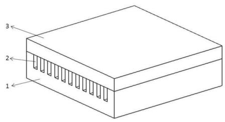
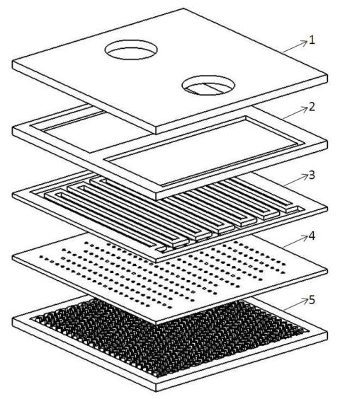
[0025] Embodiment one: see figure 2 , the prism array jet microchannel heat sink is composed of an entrance and exit structure layer 1, a liquid separation structure layer 2, an entrance and exit intersection structure layer 3, a jet structure layer 4, and a prism array structure layer 5. It is characterized in that each layer The corresponding sides have the same size and form a compact whole.

Embodiment 2

[0026] Embodiment 2: This embodiment is basically the same as Embodiment 1, and the special features are as follows: see Figure 4 , the entrances 6 and 7 of the entrance and exit structure layer 1 are round openings, which are convenient for connection with pipelines, and the material is silicon or a material with lower thermal conductivity.

[0027] see Figure 5 , the liquid separation structure layer 2 has non-through grooves 8, 9 aligned with the inlets and outlets 6, 7 and through side gaps 10, 11 on both sides, leading the liquid to the through side gaps 10, 11 on both sides. The width of the middle interlayer of the non-through grooves 8, 9 is determined according to the material properties, so as to avoid heat transfer as much as possible.

[0028] see Figure 6 , the entrance and exit intersection structure layer 3 has two intersecting comb-shaped through-slots 12, 13, the number and size of the comb-shaped through-slots 12, 13 are determined according to actual re...


PUM


Abstract

The invention relates to a prism-array jet micro-channel radiator. The radiator comprises a prism-array structure, a jet structure, an outlet-inlet cross structure, a liquid separating structure and an outlet-inlet arrangement structure. In the invention, cooling liquid enters the radiator via an inlet and then is led to side clearance through the liquid separating structure so as not to be mixedwith cooling liquid at an outlet; the distance between the outlet and the inlet is shortened by means of the comb-shaped outlet-inlet cross structure so as to reduce pressure drop; after reaching themultihole jet flow structure, the cooling liquid can be uniformly introduced onto a heated silicon substrate so that the temperature of the substrate is more uniform, heat is more easily taken away by the generated turbulent flow and meanwhile the pressure drop is also reduced by the jet structure; and finally the cooling liquid easily forms turbulent flow by means of the prism-array structure sothat the heat transferred to the prism structure from the substrate is more easily taken away, thus increasing the heat exchange efficiency. The prism-array radiator can be used in a cooler for microstructures such as an electronic chip, an LED and the like.

Description

technical field [0001] The invention relates to a novel microchannel radiator, in particular to a jet microchannel radiator adopting a prism array structure. Background technique [0002] The microchannel heat dissipation structure was first proposed by Tuckerman in 1981. He described the microchannel heat sink structure, chemically etched a number of rectangular grooves on the back of the silicon substrate of the integrated circuit, and coupled with a cover plate to form a closed coolant channel. Seal the connection with the outside world to form a coolant circuit. The heat generated by the device is conducted to the heat sink through the connecting layer, and is taken away by the coolant flowing in the microchannel to achieve the purpose of cooling the integrated circuit chip. Xiaojin Wei and Yogendra Joshi proposed a method of stacking multilayer microchannels, and preliminarily deduced the heat transfer model of this structure. The design intention of stacking several ...

Claims


Application Information

Patent Timeline
Patent Type & Authority Applications(China)
IPC IPC(8): H05K7/20
Inventor 李宗硕王小静王佳王佃晓陈玲何加猛
Owner SHANGHAI UNIV
Why Eureka
Try Eureka