Cooling water circuit for stationary engine

A technology of engine and cooling water, applied in the direction of engine cooling, engine components, machines/engines, etc.

Inactive Publication Date: 2011-04-13
YANMAR CO LTD
View PDF2 Cites 7 Cited by
  • Summary
  • Abstract
  • Description
  • Claims
  • Application Information

AI Technical Summary

Problems solved by technology

[0005] In the configuration of the cooling water circuit in the above Patent Document 1, the pressure of the suction part of the cooling water pump is approximately equal to the head pressure of the water storage tank. As long as the cooling water pump is not arranged at a position higher than the storage tank, the pressure of the suction part of the water pump cannot be reduced. set below head pressure

Method used


Image

  • Cooling water circuit for stationary engine
  • Cooling water circuit for stationary engine
  • Cooling water circuit for stationary engine

Examples


Embodiment Construction

[0050] Hereinafter, embodiments of the present invention will be described with reference to the drawings.

[0051] In this embodiment, a case where the present invention is applied to the cogeneration device 1 will be described. In addition, the combined heat and power device 1 refers to a commercial power system connected to an external commercial power source and a generator power generation system in a power transmission system to power consumers (loads), supplies the required power of the load, and recovers the accompanying energy. A system that recovers heat from heat generated by power generation.

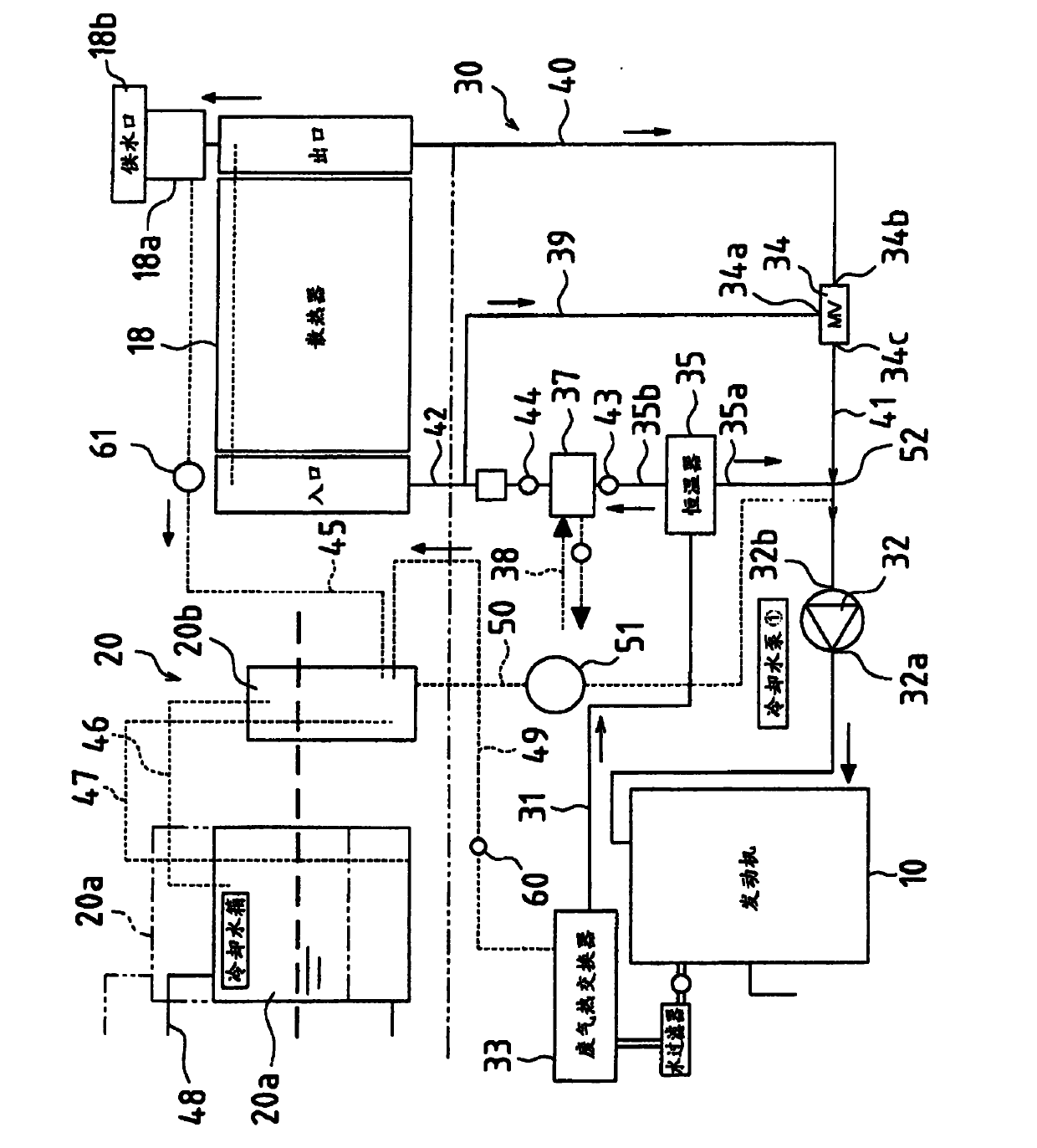
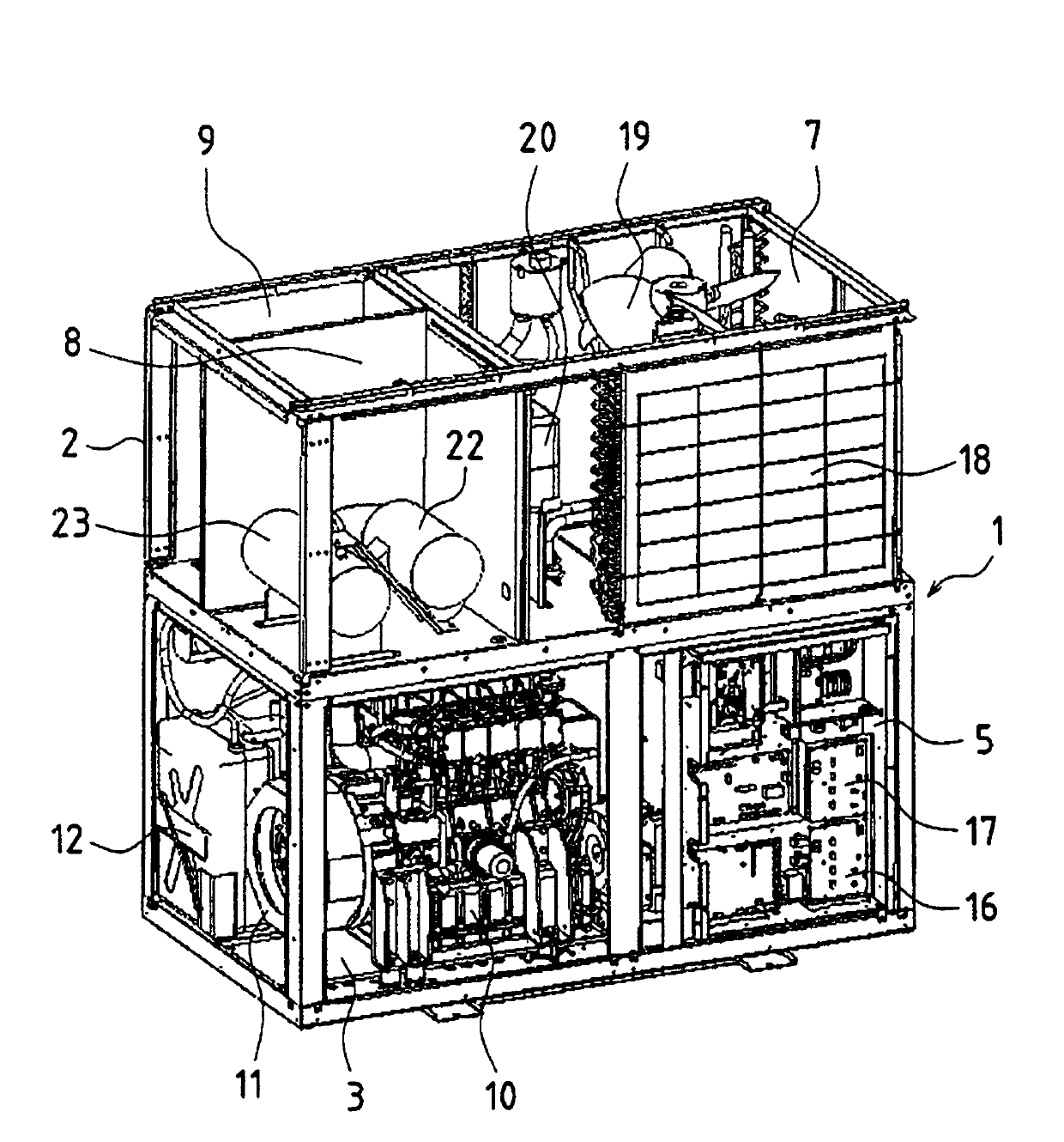
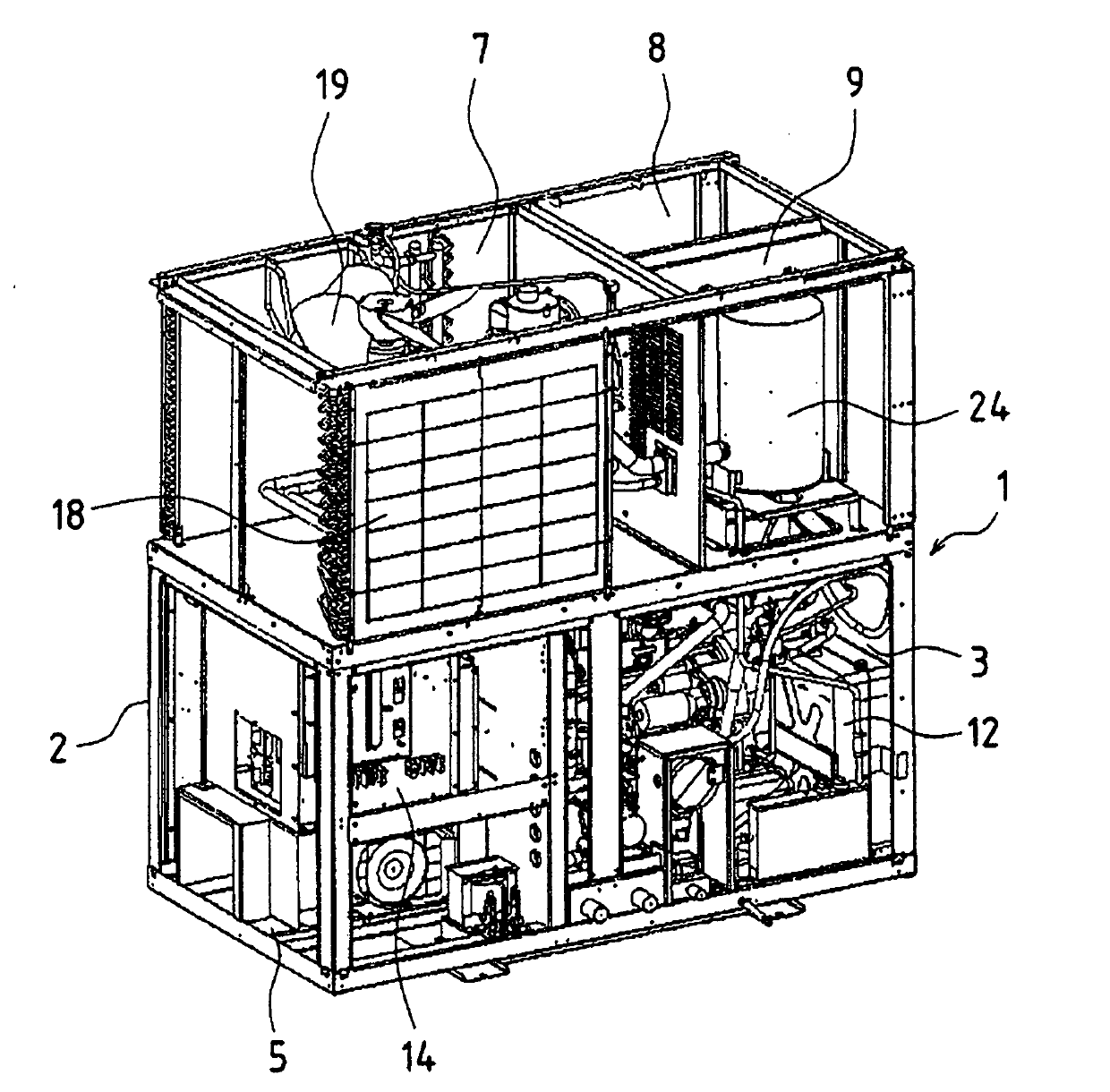
[0052] figure 1 A circuit diagram representing the engine cooling water circuit of a combined heat and power plant, figure 2 represents a frontal perspective view of the device, image 3 Represents the rear perspective view of the device.

[0053] Such as figure 2 and image 3 As shown, the cogeneration equipment 1 of the present embodiment includes a casing 2 as a c...


PUM


Abstract

The present invention has a waste heat recovery device (37) that supplies engine waste heat by way of engine coolant; a radiator (18) that dissipates engine waste heat by way of engine coolant; an exhaust gas heat exchanger (33) that supplies engine waste heat from exhaust gas to engine coolant; and a coolant pump (32) that causes engine coolant to circulate. Furthermore, the constitution is suchthat pressure drop equipment (34) is arranged upstream with respect to a coolant pump suction region (32b); a restrictor is arranged in a communication passage (50) between a coolant pump suction region and a region (20) vented to atmosphere; a location upstream with respect to the pressure drop equipment is made to communicate with the region vented to atmosphere; and the region vented to atmosphere is made capable of being kept in communication with atmosphere.

Description

technical field [0001] The present invention relates to a cooling water circuit of a stationary engine with a heat dissipation recuperator adopted in a combined heat and power system or a GHP (gas heat pump). Background technique [0002] Conventionally, as a cooling water circuit of a stationary engine having a heat radiation recovery device, a configuration in which a cooling water circuit suction part and an air opening part are communicated in an engine cooling water circuit having a heat radiation recovery device has been disclosed (for example, refer to Patent Document 1). [0003] That is, the cooling water circuit of the engine described in Patent Document 1 includes a heat dissipation recovery device in which a radiator and an outdoor heat exchanger are in contact with each other. In addition, the cooling water pump suction side is connected to the water storage tank, and the cooling water pump suction part communicates with the atmosphere through a vent hole provid...

Claims


Application Information

Patent Timeline
IPC IPC(8): F01P3/20F01P11/00
CPCF01P11/0285
Inventor 鬼原宏年天川章平林寿幸松村章二朗
Owner YANMAR CO LTD
Why Eureka
Try Eureka