Inverter control device and power conversion device

A technology of power conversion device and control device, which is applied in the direction of output power conversion device, AC motor control, control electromechanical transmission device, etc., and can solve the problems of bad influence of control and increase of output voltage, etc.

Active Publication Date: 2011-04-13
DAIKIN IND LTD
View PDF5 Cites 15 Cited by
  • Summary
  • Abstract
  • Description
  • Claims
  • Application Information

AI Technical Summary

Problems solved by technology

[0041] However, [Patent Document 2]'s figure 1 In the shown control method, the DC voltage value of the input voltage calculation and correction circuit 11 is delayed due to the delay 14 with so many time constants. , from the start of the instantaneous voltage drop to the completion of recovery, etc.), the response of the voltage calculation correction circuit 11 is delayed, which has a

Method used


Image

  • Inverter control device and power conversion device
  • Inverter control device and power conversion device
  • Inverter control device and power conversion device

Examples


no. 1 approach

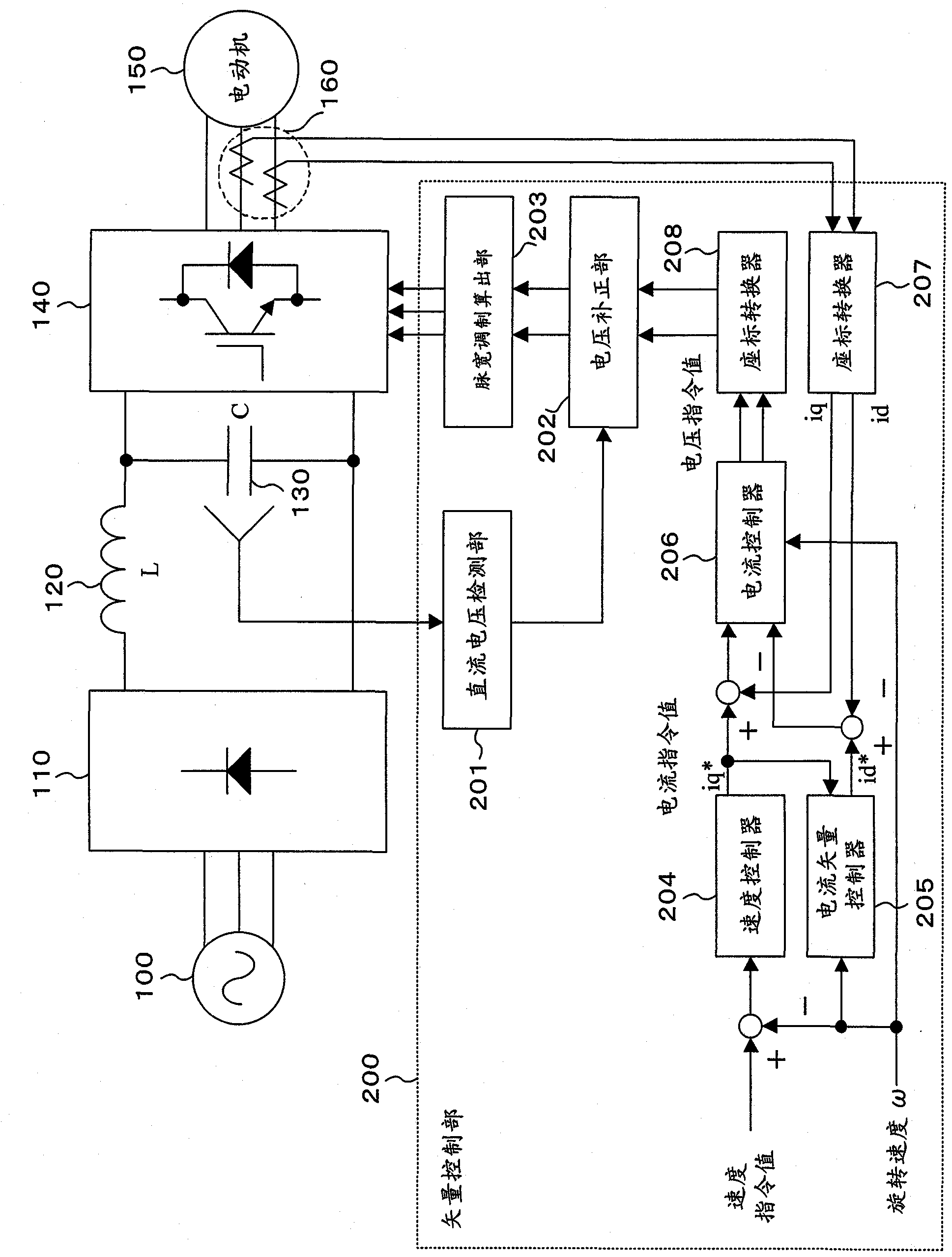
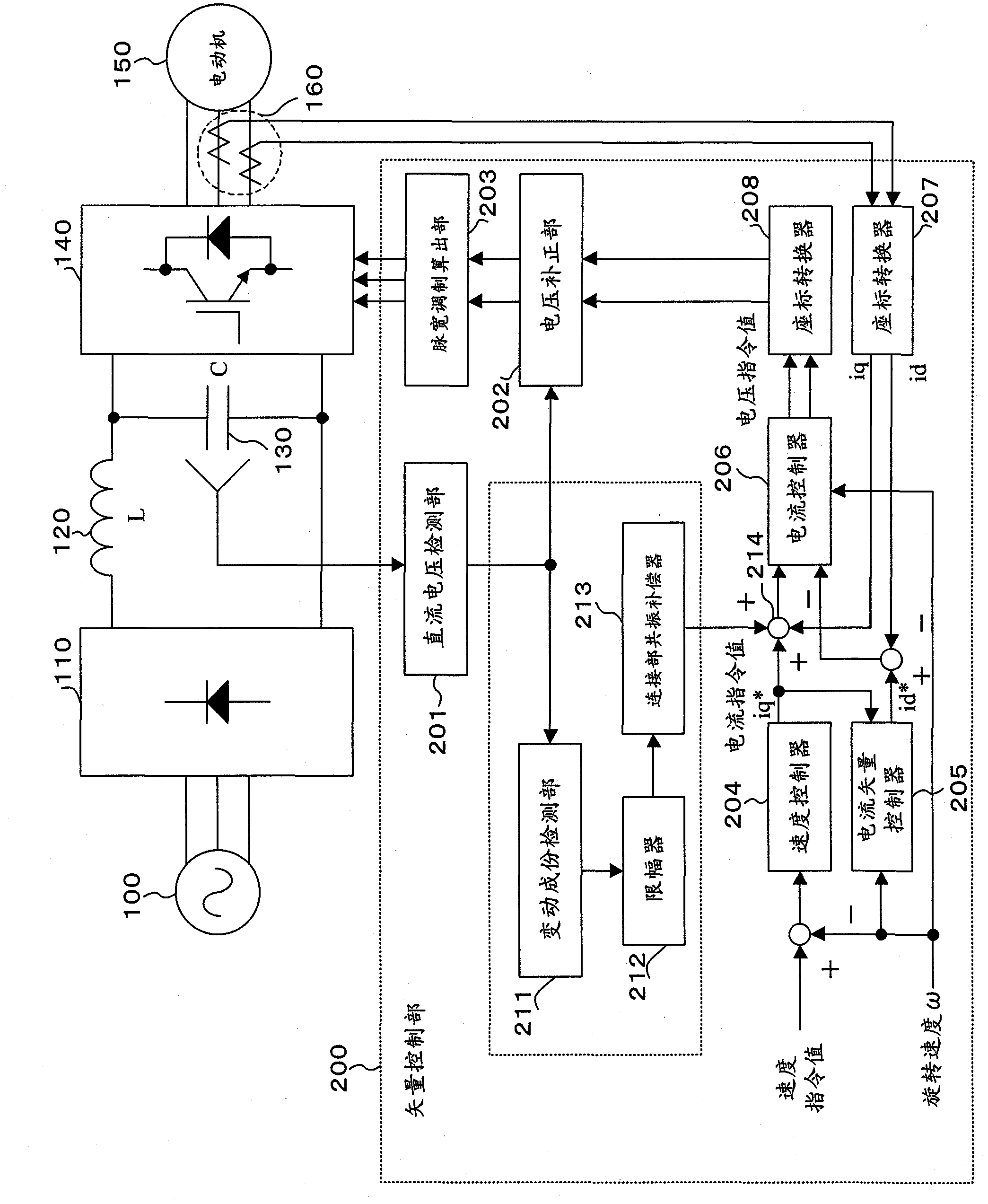
[0112] The schematic configuration of the DC / AC conversion device of the first embodiment is shown in image 3 middle. The DC-to-AC conversion device is in the figure 1 A device obtained by adding a circuit such as a fluctuation component detection unit 211 → a limiter 212 → a connection unit circuit resonance compensator 213 to the components shown.

[0113] That is, the direct-to-alternating conversion control unit 200 increases the voltage supplied to the motor from the direct-to-alternating converter 140 when the direct-current voltage increases within a predetermined frequency band in which the direct-current voltage supplied to the direct-to-alternating converter 140 fluctuates. The output voltage of the DC-AC converter, and when the DC voltage decreases, the DC-AC converter output voltage is reduced, and the DC-AC converter output voltage caused by the fluctuation of the DC voltage is suppressed outside the specified frequency band of the DC voltage. changes.

[0114...

no. 2 approach

[0156] The schematic configuration of the DC / AC conversion device of the second embodiment is shown in Image 6 middle. In the DC-AC conversion device, the image 3 On the basis of the direct-to-alternating current converter, a voltage abnormality detection unit 215 and a process of changing the limit value of the limiter 212 according to the detection result of the voltage abnormality detection unit 215 are added.

[0157] In this DC / AC conversion device, the limiting range of the limiter 212 is adjusted according to the detection result of the voltage abnormality detecting unit 215 . For example, when the voltage is abnormal, the limit range is reduced to suppress fluctuations in the output voltage by the resonance suppression control, and the limit range is increased in normal times to allow the resonance suppression control to operate normally. Thereby, it is not necessary to set a limit range for voltage abnormality, which facilitates the setting of the limit range.

...


PUM


Abstract

A DC voltage value from a DC voltage detection unit (201) is directly inputted to a voltage correction unit (202) without using a compensator or a filter. Accordingly, a voltage correction unit (202) can rapidly perform a correction process even upon a sudden voltage change such as an instantaneous power supply stop, an instantaneous voltage lowering, or a recovery from an instantaneous voltage lowering. Moreover, since a limit unit (212) limits a link resonance compensation amount to a predetermined range, it is possible to prevent an excessive fluctuation of a link resonance compensation amount upon a sudden voltage change. Moreover, the link resonance compensation amount limited to the predetermined range by the limit unit (212) is inputted to a compensator (206) of an appropriate control band in control calculation units (204 - 208). Accordingly, it is possible to avoid response of a higher speed than is necessary and perform stable control.

Description

technical field [0001] The present invention relates to a technique for controlling a DC-AC converter for driving an AC motor. Background technique [0002] In general, in a voltage-type DC / AC conversion device having a smoothing capacitor in a DC link, constant output voltage control is performed to suppress fluctuations in the output voltage due to fluctuations in the DC input voltage. figure 1 A schematic configuration of a conventional DC / AC conversion device that performs constant output voltage control is shown. in addition, figure 1 In the diagram, the control system is briefly shown, and the output current detection unit 160 is arranged between the direct current conversion unit 140 and the motor 150, but any configuration can be used as long as the current output to the motor 150 can be detected. It is a configuration in which a shunt resistor is placed in the DC connection part to detect the current. [0003] figure 1 The DC-to-AC conversion device includes a D...

Claims


Application Information

Patent Timeline
IPC IPC(8): H02P21/00F24F11/02H02P27/04H02M7/48H02P21/22H02P27/06H02P27/08
CPCH02M2007/53876H02P21/05H02P21/0003H02M5/458H02M7/53873H02M7/53876
Inventor 小川卓郎日比野宽巴正信
Owner DAIKIN IND LTD
Why Eureka
Try Eureka