Assembly welding technology of lifting frame of heating furnace

A technology for raising and lowering frames and heating furnaces, which is applied in metal processing equipment, welding equipment, manufacturing tools, etc. It can solve problems such as inability to trim, affect the assembly of beams 2, increase the workload of manual research and matching, and achieve production efficiency and product quality. Improve and reduce assembly and debugging time, and reduce the effect of manual research and matching processes

Inactive Publication Date: 2011-04-20
DATONG ELECTRIC LOCOMOTIVE OF NCR
View PDF0 Cites 8 Cited by
  • Summary
  • Abstract
  • Description
  • Claims
  • Application Information

AI Technical Summary

Problems solved by technology

[0005] 1. In the existing technology, the longitudinal beam components 11 of each section are separately assembled and welded on the platform, and then the center lines are drawn separately. After assembly, the center lines of each longitudinal beam 1 are not uniform and have deviations. The processing of each longitudinal beam 1 during processing The reference line is different. After processing, the planes of each longitudinal beam 1 are not in the same plane. After welding, aging vibration treatment is not performed, and stress deformation will occur for a period of time after processing. Since the size of the two longitudinal beams 1 is to ensure the size of the entire lifting frame The basis of precision, the corresponding dimensions on the two longitudinal beams 1 cannot be accurately corresponded, which will seriously affect the subsequent assembly of the beam 2, inclined beam 3, etc.
[0006] Two, the prior art does not include the process of pre-assembling beams and inclined beams before processing, and the two ends of the H-shaped steel that constitute the beam 2 and the inclined beams are not processed and researched, so the assembly problem of the longitudinal beam 1 cannot be found. It cannot be trimmed before processing, and the actual required size of the H-shaped steel on the beam 2 and inclined beam 3 cannot be measured according to the dimensions of the pre-assembled beam 2 and inclined beam 3, which increases the workload of manual research and matching
Use the template to determine the position of the hole on the roller mounting seat 6. This is only the theoretical hole position and size of the drawing. It does not take into account the pairing deviation of the roller mounting seat 6 and the pairing deviation of the rollers. Drill the holes first and then place the rollers. The deviation is very large. Large, the horizontal and vertical distance of the roller cannot be guaranteed, and the unsuitable holes need to be reamed
[0008] 4. In the prior art, the first stringer assembly connecting plate 121 and the second stringer assembly connecting plate 122 of the stringer assembly connecting plate 12 at the joint of the stringer 1 are drilled separately, and then in the stringer assembly 11 Drill holes separately on the H-shaped steel, and then use the holes on the first longitudinal beam assembly connecting plate 121 and the second longitudinal beam assembly connecting plate 122 to go to the holes on the H-shaped steel of the longitudinal beam assembly 11 when assembling. 12 and the H-shaped steel of the longitudinal beam assembly 11 are drilled with individual holes, and errors are prone to occur. After the holes are drilled, the holes are assembled. The verticality and concentricity of the holes cannot be guaranteed, and assembly problems are prone to occur.

Method used


Image

  • Assembly welding technology of lifting frame of heating furnace
  • Assembly welding technology of lifting frame of heating furnace
  • Assembly welding technology of lifting frame of heating furnace

Examples


Embodiment Construction

[0037] The welding process of the lifting frame of the heating furnace provided by the present invention has the following main steps:

[0038] 1. Process preparation:

[0039] 1.1 Check whether the equipment and process equipment used are in normal working condition.

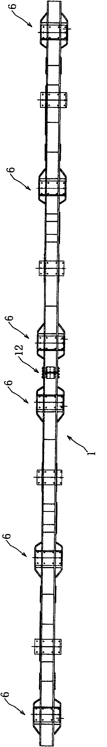
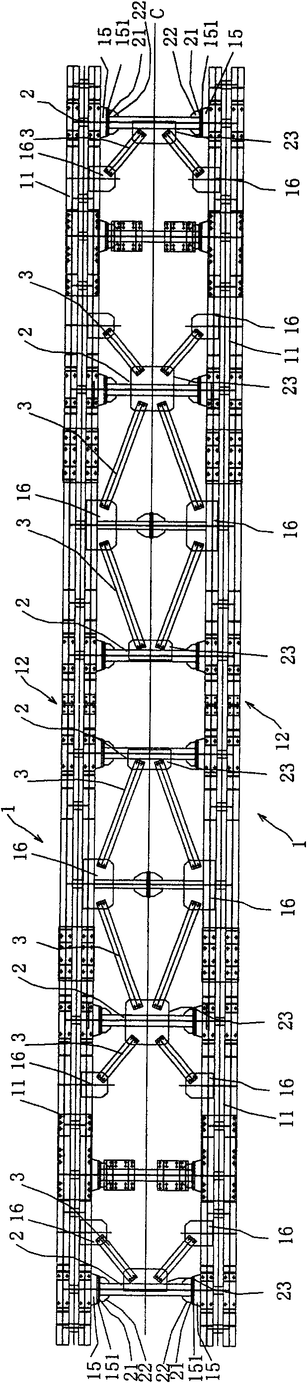
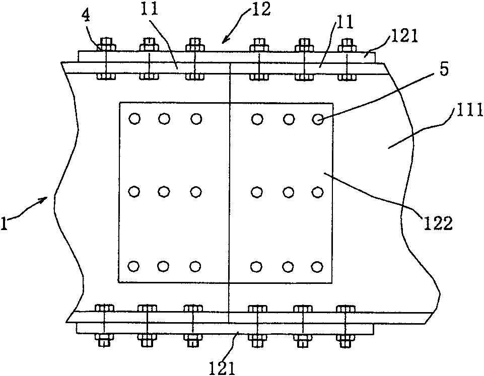
[0040] 1.2 Familiar with the drawings and technical requirements, understand the use and structure of the product, the function of each part and the connection relationship between them. The component connecting plates are connected, and the two longitudinal beam frames are made symmetrically. The frame is assembled by four sets of longitudinal beam components, ten beams and sixteen inclined beams.

[0041] 1.3 Check whether all parts are complete according to the parts list of the drawing.

[0042] 1.4 Check whether the size of the parts meets the requirements and whether the marking is correct according to the drawings.

[0043] Second, the specific process steps and content:

[0044] 1. The layout of th...


PUM


Abstract

The invention discloses an assembly welding technology of the lifting frame of a heating furnace. The lifting frame of a heating furnace comprises two longitudinal beams, a plurality of crossbeams which are transversely connected between the two longitudinal beams, and a plurality of oblique beams which are connected between the crossbeams; the assembly welding technology comprises one step, two steps, three steps or four steps selected from the following four steps: A) uniformly assembling and marking the two longitudinal beams, welding them, and subjecting them to a vibration stress relief process after welding; B) reversely assembling the integral body, utilizing holes in rollers assembled on the longitudinal beams to determine the positions of the holes of roller fitting seats on the longitudinal beams, and satisfying each dimensional requirement after welding and assembling rollers; C) preassembling and grinding the crossbeams and oblique beams, to ensure the vertical dimension of the frame; D) processing holes on connecting positions by matching drilling manner. The invention ensures the overall dimensions of the whole frame to meet the design and use requirements, and improves production efficiency and product quality greatly, moreover, saves working hours and time of assembling and debugging.

Description

technical field [0001] The invention relates to a general assembly welding process suitable for large riveted parts, in particular to a assembly welding process for a lifting frame of a walking heating furnace. Background technique [0002] The lifting frame is a key part of the bottom machinery of the walking heating furnace. It is located in the middle of the bottom machinery, specifically on the upper part of the ramp seat and the lower part of the translation frame. The seat and the upper translation frame work together. The overall size and product quality of the lifting frame directly affect the production and operation of the entire heating furnace. Such as figure 1 , 2 As shown, the lifting frame is mainly composed of two longitudinal beams 1, ten beams 2 and sixteen inclined beams 3. The beams 2 are located between the longitudinal beams 1, and the inclined beams 3 are located between the beams 2. The frame assembly is completed. Rear assembly rollers. in: [...

Claims


Application Information

Patent Timeline
Patent Type & Authority Applications(China)
IPC IPC(8): B23K31/02
Inventor 王大伟杨峰
Owner DATONG ELECTRIC LOCOMOTIVE OF NCR
Why Eureka
Try Eureka