Wound pipe heat exchanger

A coiled tube heat exchanger and coiled tube technology are applied in the field of devices for heat exchange on the wall of the tube cavity, which can solve the problems of leak detection, complicated maintenance, poor antifreeze performance, and impact on service life, etc. The probability of small mutual leakage and the effect of prolonging the service life

Inactive Publication Date: 2011-04-20
CHINA YANGZI GRP CHUZHOU YANGZI AIR CONDITIONERCO
View PDF6 Cites 9 Cited by
  • Summary
  • Abstract
  • Description
  • Claims
  • Application Information

AI Technical Summary

Problems solved by technology

But this structure also has disadvantages: (1) The pipe wall between the two media is very thin, and it is easy to flatten and leak when bent into a complex shape. When water is used as the medium, the antifreeze performance is not good at low temperatures
(2) When multiple bundles of tubes are connected in parallel, there are many solder joints, the leak detection and maintenance are complicated, and the scrap rate in the processing process is high; the solder joints are in contact with both heat transfer media, and are easily corroded, which affects the service life

Method used


Image

  • Wound pipe heat exchanger
  • Wound pipe heat exchanger
  • Wound pipe heat exchanger

Examples


specific Embodiment approach

[0029] The specific implementation, non-limiting examples are as follows:

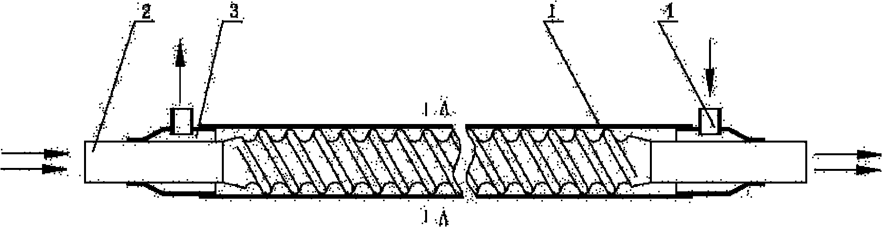
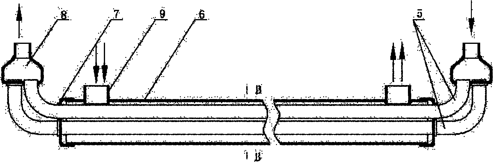
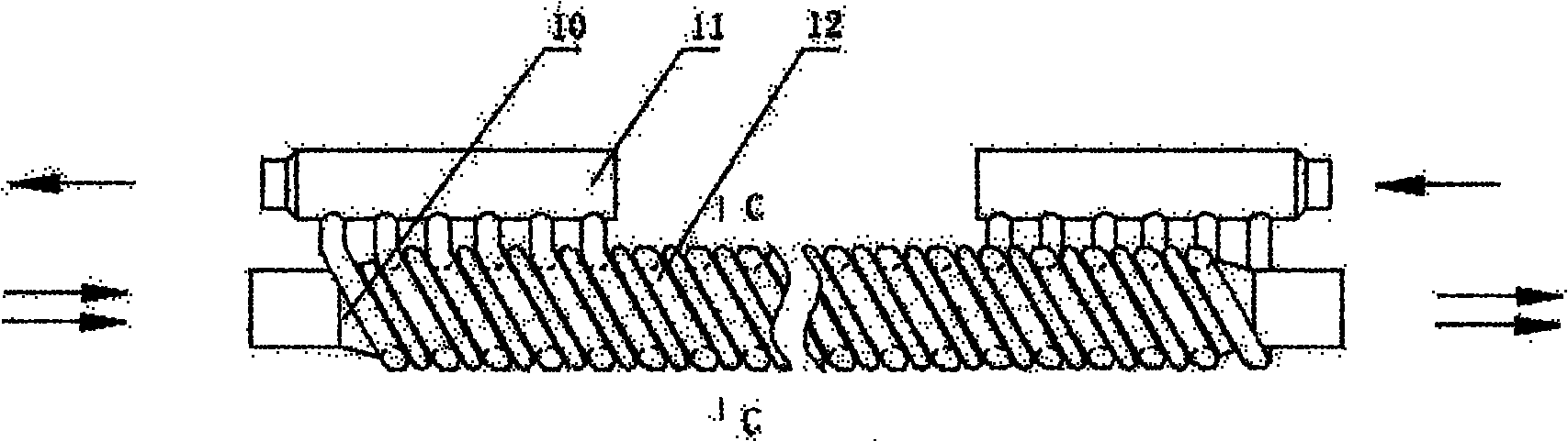
[0030] Example: such as image 3 and Figure 6 As shown, the coiled tube heat exchanger has two flow channels, the inner heat transfer tube 10 and the outer coiled tube 12. The outer surface of the inner heat transfer tube 10 is provided with six spiral grooves 10a; the outer coiled tube has a coiled tube 12a and the winding pipe inlet and outlet connecting pipe 12b are composed of two parts. There are six pieces, which are connected in parallel to form different forms of flow channels. The cross-sectional shape of the pipe 12a coincides with the cross-sectional shape of the groove, and the winding pipe 12a is helically wound in the groove of the inner heat transfer pipe; The wall surface completes the heat exchange. In this embodiment, heat-conducting glue is used on the tube wall where the inner heat transfer tube is in contact with the winding tube of the outer coiled tube to tightly bond the tub...


PUM


Abstract

The invention discloses a wound pipe heat exchanger. The wound pipe heat exchanger comprises two runners, namely a wound pipe inner heat transfer pipe (10) and an outer wound pipe (12). The wound pipe heat exchanger is characterized in that the wall surfaces of the two runners are wound to contact closely; the outer surface of the inner heat transfer pipe (10) is provided with a groove (10a); the outer wound pipe (12) consists of a wound pipe (12a) and a wound pipe inlet/outlet joint pipe (12b); the cross section shape of the wound pipe (12a) is matched with the cross section shape of the groove (10a); and the heat transfer medium in the inner heat transfer pipe (10) and the heat transfer medium in the outer wound pipe (12) flow in opposite directions and perform heat exchange through the contacted walls. The invention has the advantages of large heat exchange area, high heat transfer coefficient, reasonable runner layout, and is convenient in leak detection and maintenance and the like.

Description

technical field [0001] The invention relates to a heat exchanging device, in particular to a device in which the heat exchanging medium exchanges heat through the wall surfaces of the lumens in contact with each other. Background technique [0002] Heat exchanger is a general equipment widely used in chemical industry, power, medicine, metallurgy, refrigeration, light industry and other industries. There are many types of heat exchangers, which can be classified into tube type, plate type and other types according to the shape and structure of the heat transfer surface. Among them, the tube heat exchanger is the most widely used type of heat exchange equipment. Existing tube heat exchangers can be further divided into coil heat exchangers, casing heat exchangers, and shell and tube heat exchangers. In medium and small refrigeration equipment, the casing heat exchanger is the most widely used type of heat exchange equipment. [0003] The existing casing heat exchangers can...

Claims


Application Information

Patent Timeline
Patent Type & Authority Applications(China)
IPC IPC(8): F28D7/00F28F1/12F25B39/04
Inventor 陈凌云曾晓程沈增友
Owner CHINA YANGZI GRP CHUZHOU YANGZI AIR CONDITIONERCO
Why Eureka
Try Eureka