Efficient and controllable constant current source circuit

A constant current source and circuit technology, which is applied in the direction of adjusting electrical variables, control/regulation systems, instruments, etc., can solve the problems of inconvenient control, low efficiency of mirror current source, and inability to use digital control to achieve temperature stability Good results

Inactive Publication Date: 2011-04-20
SHANGHAI UNIV
View PDF6 Cites 4 Cited by
  • Summary
  • Abstract
  • Description
  • Claims
  • Application Information

AI Technical Summary

Problems solved by technology

However, this mirror current source has the following disadvantages: one, the operating currents of the two triodes forming the mirror current source are equal, but only one transistor is doing effective work, so that the efficiency of the mirror current source is not high, and with the drive current Second,

Method used


Image

  • Efficient and controllable constant current source circuit
  • Efficient and controllable constant current source circuit
  • Efficient and controllable constant current source circuit

Examples


Embodiment 1

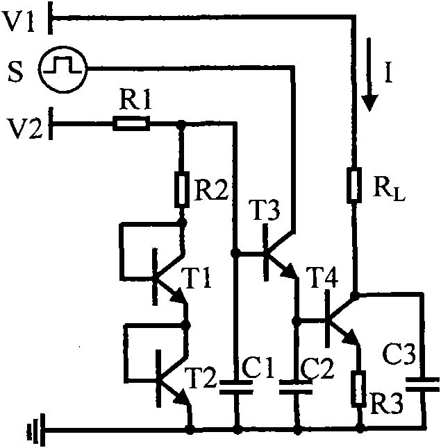
[0026] Preferred embodiment of the present invention is described in detail as follows in conjunction with accompanying drawing: See figure 2 , the high-efficiency controllable constant current source circuit includes four transistors T1, T2, T3, T4, three resistors R1, R2, R3 and one load RL. T1 and T3, T2 and T4 are packaged in two pairs of tubes respectively, T1 tube to T3 tube, T2 tube to T4 tube for temperature compensation. C1, C2 and C3 are mainly to prevent overshoot, and their value is around 1nF, which is adjusted according to the frequency of the control signal S. from figure 2 It can be seen from the circuit of high-efficiency controllable constant current source that the base voltage of transistor T3 is:

[0027] V b 3 = V b 1 + V b 2 + V ...

Embodiment 2

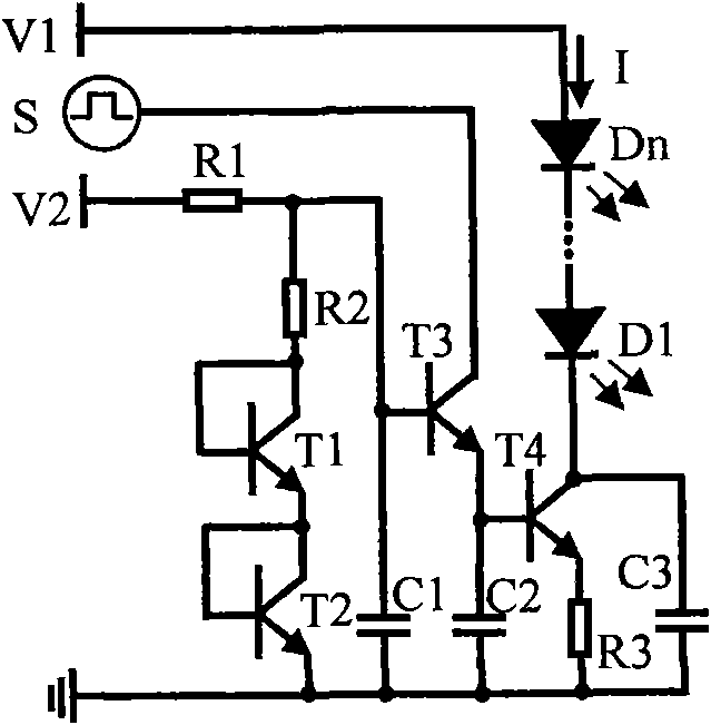
[0034] In LED backlighting and lighting applications, LEDs must be driven by a constant current source with a current of about 20mA. Using the high-efficiency controllable constant current source drive of the second embodiment such as image 3 As shown, if the reference voltage V2 is 12V, R1 is 18.2K ohms, R2 is 3K ohms, and R3 is 75 ohms. Therefore, the constant current source current, that is, the LED drive current is

[0035] I = 20.000 mA + Δ VR 2 ( R 1 + R 2 ) R 3

[0036] = 20.000 mA + 1.89 ΔVmA

[0037] If the error of the reference voltage is less than 0.2V...

Embodiment 3

[0039] If multiple high-efficiency controllable constant current sources are required in the application, and the current of each branch is the same, the third example of this embodiment Figure 4 The method shown is extended to save components and reduce cost. T4, T5, ..., Tn use the same type of triode, and their power consumption is basically the same. T2 tube also has a temperature compensation function for T4, T5, ..., Tn tube, and the temperature stability of the constant current source is guaranteed. Therefore, after expansion, the advantages of the high-efficiency controllable constant current source still exist.


PUM


Abstract

The invention relates to an efficient and controllable constant current source circuit. The circuit comprises n triodes, n-1 resistors and n-3 paths of loads, wherein n is a natural number which is more than 3; and the two triodes are packaged in a geminate transistor and have the same working environment. Because an emitter junction of one triode provides a bias voltage for the other triode to compensate the temperature influence, a constant current source has favorable temperature stability performance; because the current of a control end of the constant current source is very low and a majority of current passes by the loads, the working efficiency of the constant current source is higher; because the triode at the control end works in the two states of the triode and the diode, the constant current source is flexibly controlled by utilizing a digital mode; and because parameters of the four triodes are not strictly required, the constant current source can be realized by utilizing a parse element.

Description

technical field [0001] The invention relates to a constant current source circuit, in particular to a high-efficiency controllable constant current source circuit with high working efficiency and digital control. Background technique [0002] A constant current source is a stable power supply whose output current has nothing to do with its external influence. Constant current sources are widely used in various circuits, and occupy an important position in the fields of instrumentation, electronic equipment, and high-tech science and technology. A constant current source can be used as figure 1 shown in the mirror current source to achieve. If the parameters of the transistors T1 and T2 are exactly the same, the collector currents IC1 and IC2 flowing through the two tubes are the same. Depend on figure 1 It can be known that the reference current is [0003] I REF = I C 1 ...

Claims


Application Information

Patent Timeline
IPC IPC(8): G05F3/26
Inventor 陈光化王安琪金民伟邵勇
Owner SHANGHAI UNIV
Why Eureka
Try Eureka