Microresistor assembly

A technology of micro-resistors and components, applied in the manufacture of resistor parts, resistors, resistors, etc., can solve the problems of limited operating power, short circuit, limited heat dissipation effect, etc., to achieve increased heat dissipation area and accurate measurement results , The effect of improving thermal stability

Active Publication Date: 2011-04-20
CYNTEC
View PDF2 Cites 11 Cited by
  • Summary
  • Abstract
  • Description
  • Claims
  • Application Information

AI Technical Summary

Problems solved by technology

During the stamping process, there will be burrs or protrusions on the surface of the body and the heat sink. These burrs or protrusions may pierce the adhesive layer (thickness is about 30 μm) used for pressing or adhesion during the bonding process of the body and the heat sink. A short circuit is formed in contact with the heat sink, resulting in the resistance value of the micro-resistance component failing to meet the preset requirements
Furthermore, the micro-resistance component uses two rectangular heat sinks symmetrically arranged at both ends of the body, so it can only take away the heat energy at both ends of the body, but cannot take away the heat energy of the central part of the body with a higher temperature, so the body The heat dissipation effect on the surface is limited, so that the operating power that can be increased is limited

Method used


Image

  • Microresistor assembly
  • Microresistor assembly
  • Microresistor assembly

Examples


Embodiment Construction

[0042] Relevant technical content and detailed description of the present invention, cooperate drawing description as follows:

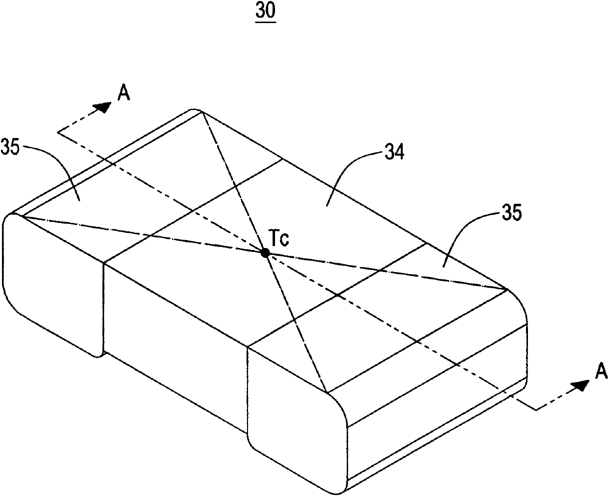
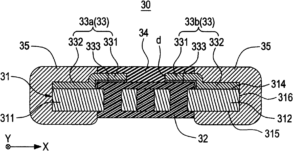
[0043] refer to figure 1 and figure 2 The micro-resistor assembly 30 of the first preferred embodiment of the present invention includes a resistor body 31 , a first protection layer 32 , at least one heat conduction layer 33 , a second protection layer 34 , and two electrode layers 35 .

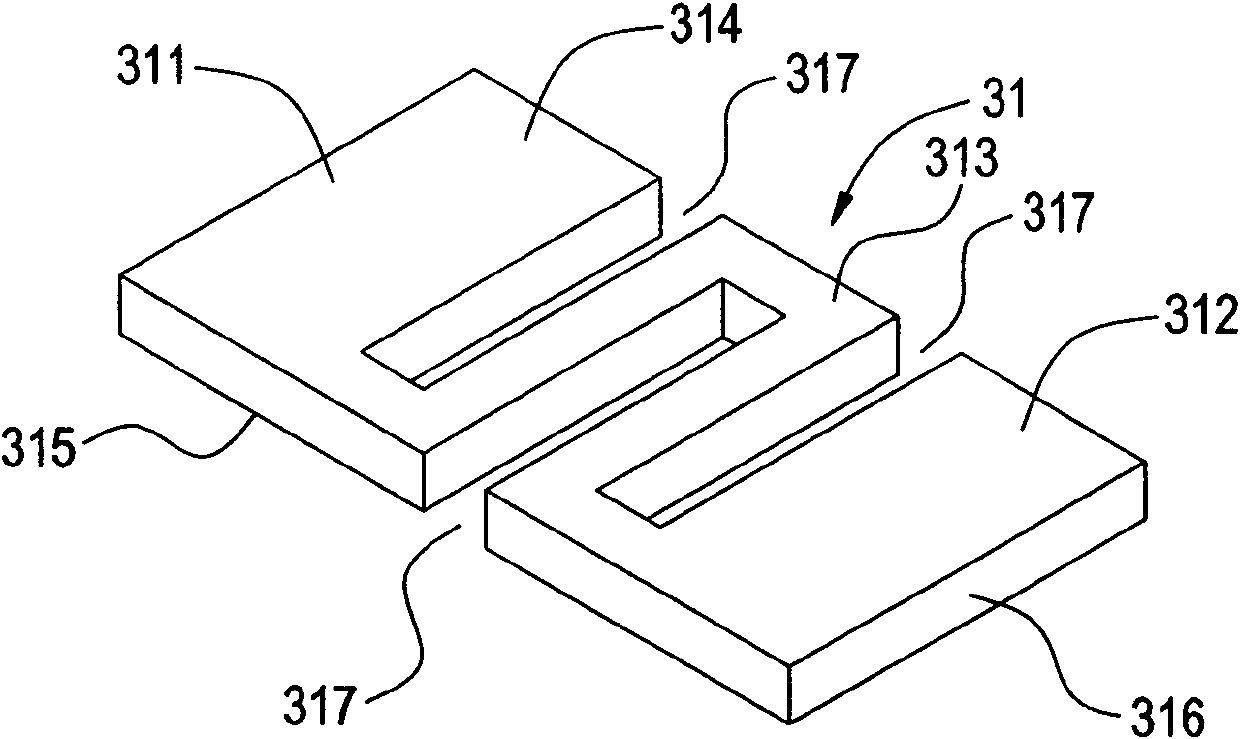
[0044] refer to image 3 , the resistor body 31 is a metal sheet and has a first end portion 311, a second end portion 312 opposite to the first end portion 311 and a central portion 313 between the first end portion 311 and the second end portion 312 . The resistor body 31 also has a first surface 314 , a second surface 315 opposite to the first surface 314 , and a plurality of side surfaces 316 connecting the first surface 314 and the second surface 315 . In this embodiment, the central portion 313 of the resistor body 31 has a plurality of through holes 317...


PUM


Abstract

The invention relates to a microresistor assembly comprising a resistor body, a first protective layer, a heat conducting layer, a second protective layer and two electrode layers, wherein the resistor body is provided with a first end part, a second end part and a center part, wherein the first end part and the second end part are opposite, and the center part is positioned between the first endpart and the second end part; the resistor body defines a center line; the first protective layer is arranged on a part of the center part of the resistor body and exposes the first end part and the second end part; the heat conducting layer is formed on a part of the resistor body in a depositing way; the second protective layer are arranged on a part of the heat conducting layer; and the two electrode layers respectively wrap the first end part and the second end part of the resistor body and are electrically connected with the heat conducting layer.

Description

technical field [0001] The invention relates to an electronic component, in particular to a micro-resistance component. Background technique [0002] With the continuous development of electronic circuit technology, the requirement for the stability of the resistance value of the resistance component is increasingly higher. The temperature coefficient of resistance (Temperature Coefficient of Resistance, TCR) and other properties of traditional chip resistor components have gradually been unable to meet the requirements of high stability, which has limited their applications. [0003] In order to improve the thermal stability of the resistance value of the resistance component, Taiwan Invention Patent Publication No. 200830333 and No. 200830334 propose a micro-resistor component. By forming a high-performance radiator on one side of the resistance component body, the heat energy on the resistance component body is dissipated, so as to achieve the purpose of improving the op...

Claims


Application Information

Patent Timeline
Patent Type & Authority Applications(China)
IPC IPC(8): H01C1/084H01C17/00
Inventor 陈璟锋施坤宏林彦霆叶银田
Owner CYNTEC
Why Eureka
Try Eureka