
System and method for improving beam current intensity distribution after leading ion beam out

A technology of ion beam and beam current, which is applied in the direction of discharge tubes, electrical components, circuits, etc., can solve the problems of unfavorable time efficiency, long time required, and reduction of beam current, so as to improve the distribution of beam current intensity and reduce beam current Effects of loss and beam enhancement

Active Publication Date: 2012-07-18
KINGSTONE SEMICONDUCTOR LIMITED COMPANY
View PDF1 Cites 0 Cited by
  • Summary
  • Abstract
  • Description
  • Claims
  • Application Information

AI Technical Summary

Problems solved by technology

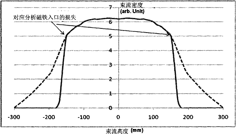
In order to obtain a uniform beam intensity distribution, the geometric convex surface of the extraction electrode is made more convex, so that more of the middle beam moves to the edge, As a result, more beam current will be blocked and lost by the entrance of the analysis magnet, so that the beam current that can be transmitted to the wafer is greatly reduced. For the ion implantation process, the process of the same implant dose will take longer , which is very detrimental to the time efficiency of the entire process

Method used


Image

  • System and method for improving beam current intensity distribution after leading ion beam out
  • System and method for improving beam current intensity distribution after leading ion beam out
  • System and method for improving beam current intensity distribution after leading ion beam out

Examples


Embodiment Construction

[0034] based on the following Figure 3 ~ Figure 8 , specify the preferred embodiment of the present invention:

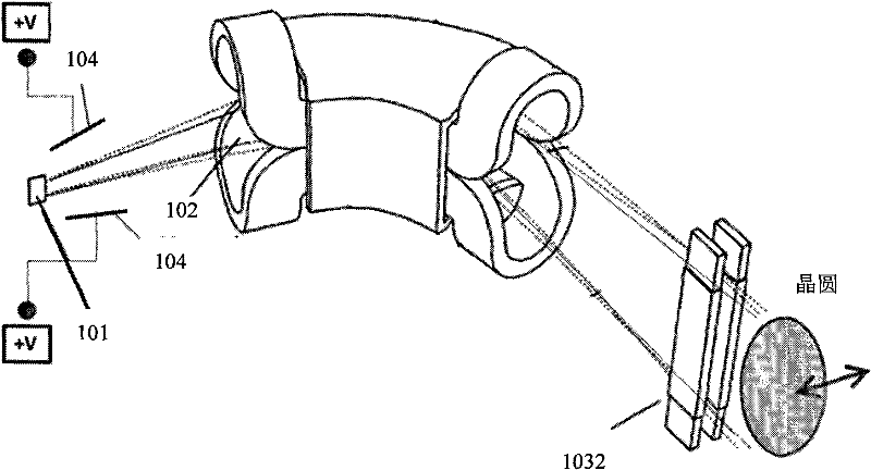
[0035] Such as image 3 As shown, it is a system to improve the beam intensity distribution after the ion beam is extracted, including:

[0036] The ion source generates an ion beam;

[0037] The beam extraction system 101 is used to obtain divergent ion beams through divergent extraction electrodes;

[0038] Mass analysis magnet 102 for selecting the ion beam of required energy;

[0039] The beam uniformity controller 1031 is used to adjust the density distribution of the beam in the longitudinal direction; in this embodiment, while adjusting the density distribution of the beam in the longitudinal direction, the beam uniformity controller 1031 can also realize the first The function of an angle controller;

[0040] The calibrator 1032 terminates the divergence tendency of the beam current, and makes the beam current propagate in parallel to control the injec...


PUM


Abstract

The invention discloses a system and a method for improving beam current intensity distribution after leading an ion beam out. A positive bias current-conducting plate is added between the top part and the bottom part of a beam current path between a beam current leading-out system and a mass analysis magnet, wherein the positive bias current-conducting plate can generate an electric field so that part beam current is pressed to the middle part; a bias voltage can modulate beam current intensity to increase the beam current intensity, so that the beam current loss caused by the mass analysis magnet is compensated; and simultaneously, some nonlinear angle changes caused by the positive bias current-conducting plate is independently corrected by utilizing an angle controller. By using the system and the method, the beam current loss caused by an analysis magnet inlet can be reduced; high beam current transmission efficiency is achieved by greatly improving the beam current of an analysis magnet; and the density distribution of the beam current can be optimized more conveniently when the beam current uniformity distribution is adjusted.

Description

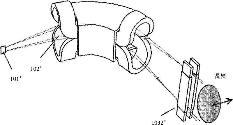
technical field [0001] The invention relates to the field of semiconductor manufacturing, in particular to a system and method for improving the distribution of beam current intensity after ion beam extraction. Background technique [0002] As the production of semiconductor products tends to process larger semiconductor wafers (from 8 inches to 12 inches, and has now developed to 18 inches), single wafer processes (processing one wafer at a time) have recently been widely adopted. [0003] Ion implantation is a process of doping impurities in a semiconductor substrate to change the electrical properties and material properties of the substrate. There are several different processes for doping single wafers. One such approach is disclosed in US Patent 7,326,941. Such as figure 1 As shown, the ion implantation device described in this patent includes an ion source, an extraction system 101' for extracting an ion beam through a divergent extraction system, a mass analysis m...

Claims


Application Information

Patent Timeline
Patent Type & Authority Patents(China)
IPC IPC(8): H01J37/04H01J37/317
Inventor 陈炯
Owner KINGSTONE SEMICONDUCTOR LIMITED COMPANY
Learn More