Digital slope compensation for current mode control

一种斜率补偿、数字的技术,应用在数字斜率补偿装置领域,能够解决振荡等问题,达到实现响应时间、最小响应时间、减少数目的效果

Active Publication Date: 2011-04-20
DELTA ELECTRONICS (THAILAND) PUBLIC CO LTD
View PDF7 Cites 43 Cited by
  • Summary
  • Abstract
  • Description
  • Claims
  • Application Information

AI Technical Summary

Problems solved by technology

[0007] However, there are multiple disadvantages of peak current mode control in CCM: control loosens stability, causes sub-harmonic oscillations if duty cycle exceeds 50%, caused by peak rather than average current sensing and noise sensitivity Non-ideal control response, especially at small inductor current ripple
However, the implementation of slope compensation in digital control remains challenging because a continuously increasing ramp function is required during each switching cycle

Method used


Image

  • Digital slope compensation for current mode control
  • Digital slope compensation for current mode control
  • Digital slope compensation for current mode control

Examples


Embodiment Construction

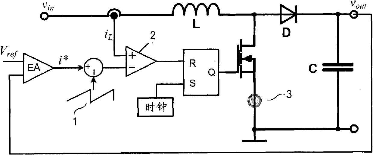
[0040] Current mode control is well known in the art. exist figure 1 The control block of a boost converter with an outer voltage loop and an inner peak current control loop with analog slope compensation is shown in . The rationale for peak current mode control and the need for slope compensation is as follows.

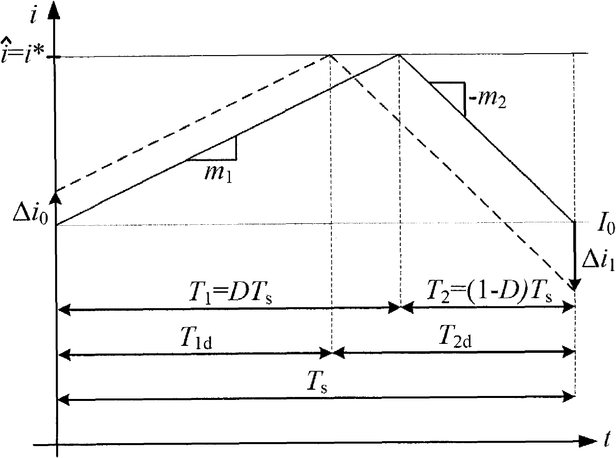
[0041] In order to derive a stability criterion for a peak current mode controlled CCM converter characterizing the transition to subharmonic oscillation, operation without slope compensation should be analyzed in a first step. Therefore, we refer to figure 2 , where the undisturbed (solid line) and disturbed (dashed line) inductor currents are plotted against a single switching period Ts. Both inductor current shapes have the same rising slope m1, falling slope m2 and peak value

[0042] For the interference-free case ( figure 2 As far as the solid line in ) is concerned, it can be directly derived

[0043] i ^ = ...


PUM


Abstract

A digital slope compensation apparatus and method for a switched-mode power supply use a sensor for sensing and generating an analog inductor current ( i L ) of the switched-mode power supply, a comparator (2) for generating a trigger signal according to a comparison of an analog current threshold level and the analog inductor current ( i L ), and a pulse width modulator (PWM) for controlling the operation of a switched-mode power supply, wherein the pulse width modulator (PWM) is arranged to be triggered by the trigger signal of the comparator. A first analog to digital converter is arranged for converting an analog output voltage ( V out ) of the switched-mode power supply into a digital output voltage, means are arranged for transforming the digital output voltage into a digital current threshold level ( i cmp ), and a digital to analog converter is arranged for generating the analog current threshold level according to the digital current threshold level ( i cmp ).

Description

technical field [0001] The present invention relates to a digital slope compensation arrangement for a switched mode power supply, wherein a sensor is used to sense an analog inductor current of a switched mode power supply and a comparator is used to determine the A trigger signal is generated and a pulse width modulator is used to control the operation of the switched mode power supply, wherein the pulse width modulator is arranged to be triggered by the trigger signal of the comparator. The invention also relates to a digital slope compensation method for a switched mode power supply, wherein the analog inductor current of the switched mode power supply is sensed, a trigger signal based on a comparison of the analog current threshold level and the simulated inductor current is generated, and the pulse is triggered by the trigger signal wide modulated signal to control the operation of a switching mode power supply. Background technique [0002] Current mode control is a ...

Claims


Application Information

Patent Timeline
Patent Type & Authority Applications(China)
IPC IPC(8): H02M3/155
CPCH02M3/156
Inventor F·沙夫迈斯特T·格罗特
Owner DELTA ELECTRONICS (THAILAND) PUBLIC CO LTD
Why Eureka
Try Eureka