Light emitting diode driving circuit

A technology of light-emitting diodes and driving circuits, which is applied in the direction of circuit layout, lamp circuit layout, light source, etc., can solve the problems of accelerating light-emitting diode light decay and burning, poor lighting device efficiency, and affecting the normal operation of light-emitting diode modules, etc., to achieve good assembly The effect of flexibility

Inactive Publication Date: 2013-06-19
江苏博悦物联网技术有限公司
View PDF1 Cites 0 Cited by
  • Summary
  • Abstract
  • Description
  • Claims
  • Application Information

AI Technical Summary

Problems solved by technology

[0004] There are generally two types of existing light-emitting diode drive circuits. One is to use a constant-voltage power supply with a current-limiting resistor to limit the current of the light-emitting diode. The efficiency of the lighting device is poor; the other is to use the power supply of the constant current source to directly output the constant current to the LED. However, when this method drives the LED module at the same time, the LED module included Multiple light emitting diodes are connected in parallel, and the current output by the constant current source is the sum of the rated currents of the multiple light emitting diodes, but when one or more light emitting diodes burn out, the current flowing through other normal working light emitting diodes is greater than Its rated current will inevitably accelerate the light decay or even burn out of the plurality of normally working LEDs, thereby affecting the normal operation of the entire LED module.

Method used


Image

  • Light emitting diode driving circuit

Examples


Embodiment Construction

[0009] The embodiments of the present invention will be further described in detail below in conjunction with the accompanying drawings.

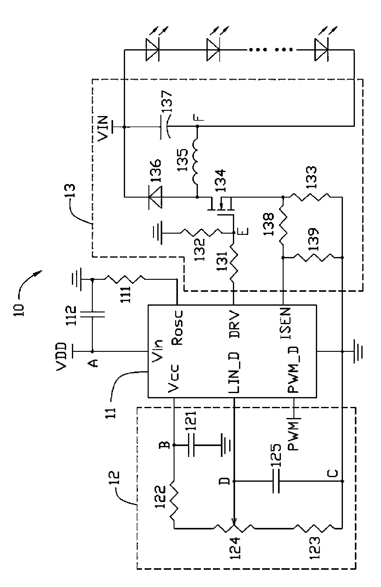
[0010] See figure 1 , an LED driving circuit 10 provided by an embodiment of the present invention includes a pulse width modulation control chip 11 , an input unit 12 and an output unit 13 .

[0011] The pulse width modulation control chip 11 is provided with a plurality of basic pins, which include a Vin pin, a Vcc pin, a LIN_D pin, a PWM_D pin, a GND pin, an ISEN pin, a DRV pin, and a Rosc pin . In this embodiment, the PWM control chip 11 is an integrated chip FP6700, which can support high voltage and buck architectures, and its output current can be greater than 1 ampere. Among them, the integrated chip FP6700 is a driver chip disclosed by Tianyu Technology Co., Ltd. on April 1, 2008.

[0012] The Vin pin of the integrated chip FP6700 is electrically connected to an external voltage VDD, and the electrical connection is defined as a...


PUM


Abstract

The invention relates to a light emitting diode driving circuit with adjustable output current, which comprises a pulse-width modulation control chip, an input unit and an output unit, wherein a PWM-D (Pulse Width Modulation-Digital) pin of the pulse-width modulation control chip is electrically connected with a pulse-width modulation signal, a slide end of a slide theostat arranged in the input unit is electrically connected with an LIN-D (Linear-Digital) pin of the pulse-width modulation control chip, a source electrode of N groove reinforcing type MOSFETs (Metal-Oxide -Semiconductor Field Effect Transistors) arranged in the output unit is electrically connected with an ISEN pin of the pulse-width modulation control chip through a second resistor, a drain electrode is electrically connected with one end of an inductor and a positive electrode of a fast diode, a first capacitor is electrically connected between the other end of the inductor and the negative electrode of the fast diode, and both ends of the first capacitor are output ends of the light emitting diode driving circuit and are electrically connected with a light emitting diode module for driving the light emitting diode module.

Description

technical field [0001] The invention relates to a light emitting diode driving circuit, in particular to a light emitting diode driving circuit with adjustable output current. Background technique [0002] With the development of science and technology and the progress of society, there are more and more types of electronic products, and the integration degree of integrated circuits in electronic products is also getting higher and higher. Most of the electronic products need to apply a stable DC voltage to make them work. [0003] The LED drive circuit is mainly used to adjust the input DC voltage level and stabilize it at a set voltage value. It generates pulse waves by driving the switching of the power components of the upper bridge and the lower bridge. The pulse wave passes through a low-pass filter composed of inductors and capacitors to generate a stable DC voltage to supply various electronic products. For details, please refer to "HIGH INPUT VOLTAGE STEP-DOWN DC-D...

Claims


Application Information

Patent Timeline
Patent Type & Authority Patents(China)
IPC IPC(8): H05B37/00H05B37/02F21V23/00F21Y101/02
Inventor 洪隆裕孔圣翔陈世权赖志铭
Owner 江苏博悦物联网技术有限公司
Why Eureka
Try Eureka