
Vehicle brake control device and method

A control device and vehicle braking technology, applied in vehicle components, electric braking system, deceleration device components, etc., can solve problems such as affecting driving safety, system complexity, affecting riding comfort, etc., to extend working life, reduce Thermal decay, simple structure effect

Inactive Publication Date: 2011-04-27
袁三友 +2
View PDF9 Cites 2 Cited by
  • Summary
  • Abstract
  • Description
  • Claims
  • Application Information

AI Technical Summary

Problems solved by technology

[0010] The retarder control method described above, due to the consideration of multiple factors, the system is relatively complex, and the reliability and stability of the work have yet to be tested in practice
As far as the former two are concerned, there are still the following problems in the independent control of the main brake and the eddy current retarder of the braking system: 1. Each device of the braking system requires a certain operation by the driver, and this operation is usually Different from the traditional braking operation mode, in addition to increasing the labor intensity of the driver, it is also easy to cause misoperation during the braking process; 2. The independent operation of each device in the braking system is not conducive to mutual interaction during the braking process of the car. With coordinated work, it is easy to cause excessive braking - affecting ride comfort, or insufficient braking - affecting driving safety

Method used


Image

  • Vehicle brake control device and method
  • Vehicle brake control device and method

Examples


Embodiment Construction

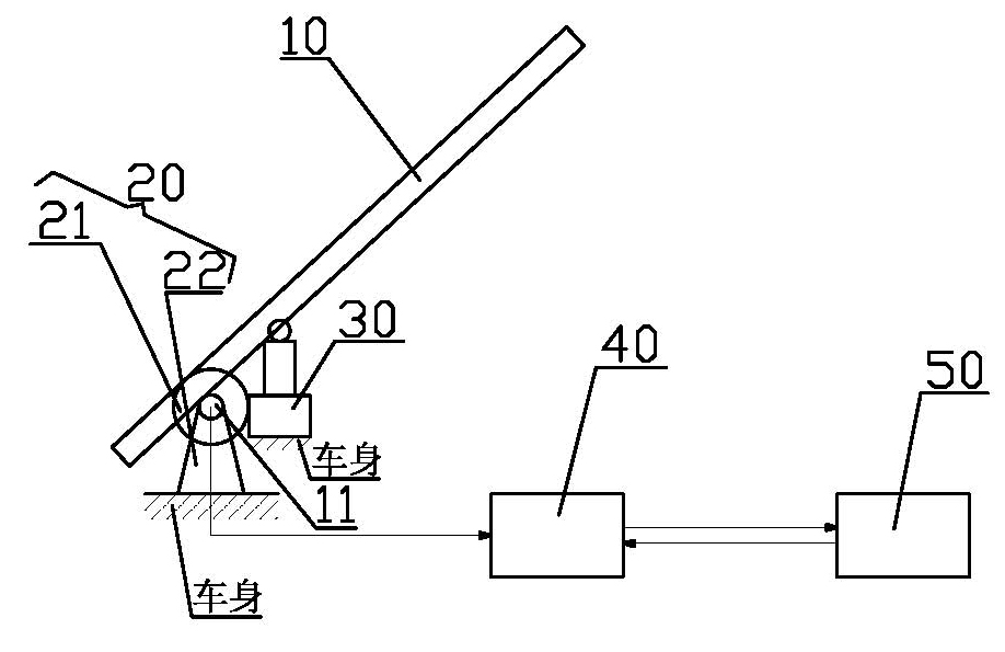
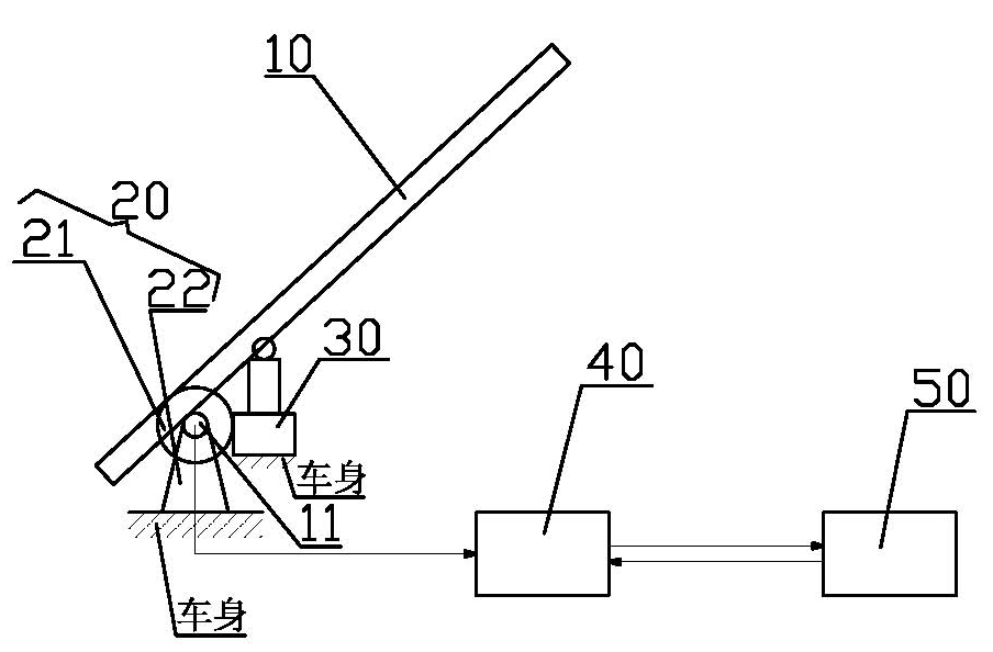
[0026] The vehicle braking control device of the present invention includes a brake pedal 10 originally installed on the vehicle and a main brake 30 fixed on the inner bottom of the vehicle body and connected to the brake pedal 10, and also includes an angle sensor 20, which includes a rotating shaft 21 and casing 22, the rotating shaft 21 is fixedly connected on the pedal shaft 11 of the original brake pedal 10 of the existing vehicle, the casing 22 is coaxially sleeved on the rotating shaft 21 and is fixedly connected between the brake pedal 10, the casing 22 and the rotating shaft 21 It is a clearance fit and can be rotated relative to each other. Angle sensing elements (not shown in the figure) are respectively arranged on the rotating shaft 21 and the housing 22 to measure the angle change during the relative rotation between the two.

[0027] The vehicle braking control device of the present invention also includes an eddy current retarder excitation winding work sequenc...


PUM


Abstract

The invention relates to a vehicle brake control device. The vehicle brake control device comprises an angle sensor and an eddy current retarder excitation winding working sequence controller which is electrically connected with the angle sensor and an eddy current retarder, wherein the angle sensor comprises a rotating shaft and a shell; the rotating shaft and the shell are provided with angle sensing components respectively; the angle sensing components are used for measuring the angle change when the rotating shaft and the shell are rotated relative to each other; and the eddy current retarder excitation winding working sequence controller is a logic control circuit and is used for controlling the working state of the original eddy current retarder excitation winding working control circuit of a vehicle according to brake angle information transmitted by the angle sensor. The vehicle brake control device exerts the effect of the eddy current retarder completely, reduces the abrasion of a brake shoe of a main brake and the heat fading of the braking efficiency as far as possible, prolongs the working life of the eddy current retarder, has a simple structure and low price, is convenient to butt, and conforms to a driving operation habit.

Description

technical field [0001] The invention relates to the technical field of vehicle braking control, in particular to a novel vehicle braking control device and control method. Background technique [0002] At present, when the eddy current retarder of most automobiles works in conjunction with the original main brake of the vehicle, the following problems generally exist: [0003] When the brake pedal is controlled, the eddy current retarder and the original main brake of the vehicle work in parallel throughout the whole process - when the pedal is stepped on, the braking state is entered at the same time; when the pedal is released, the braking state is released at the same time. [0004] This full-range synchronous working mode fails to reduce the working frequency of the main brake friction plate, and cannot fully play the role of the retarder. [0005] The working sequence of the excitation windings of the eddy current retarder is fixed, resulting in a large difference in t...

Claims


Application Information

Patent Timeline
IPC IPC(8): B60L7/28H02P3/04
CPCY02T10/642Y02T10/64
Inventor 袁三友陈勃生袁翔
Owner 袁三友
Learn More