
Hydraulic braking system for megawatt fan

A hydraulic braking, megawatt-level technology, applied in the field of wind power generation, can solve the problems of slow braking action, damage to the fan, short service life of the motor pump, etc., and achieve the effect of smooth yaw braking, uniform force, and extended life

Inactive Publication Date: 2011-04-27
SHANGHAI HUIYI CONTROL SYST
View PDF0 Cites 7 Cited by
  • Summary
  • Abstract
  • Description
  • Claims
  • Application Information

AI Technical Summary

Problems solved by technology

[0003] The hydraulic braking system of the existing megawatt fan has the following defects: 1) Since the motor pump is used as the power source of the brake actuator, when the system loses power or the motor pump fails, the brake actuator will lose the power source. 2) During the yaw braking process of the wind turbine, the existing system controls the oil supply flow and yaw pressure of the yaw brake to be unstable, so the stability and reliability of the wind turbine yaw brake Poor, uneven force on yaw power components, easy to be damaged due to fatigue impact; 3) The existing system needs to continue to use hydraulic oil when the fan is uncabled, so the service life of the motor pump is short; 4) The main shaft brake When the actuator needs to brake at high speed, the braking action will be slow due to the insufficient power provided by the motor pump, which will easily damage the fan

Method used


Image

  • Hydraulic braking system for megawatt fan
  • Hydraulic braking system for megawatt fan
  • Hydraulic braking system for megawatt fan

Examples


Embodiment Construction

[0022] The embodiments of the present invention will be described in further detail below in conjunction with the accompanying drawings, but the present embodiments are not intended to limit the present invention, and any similar structures and similar changes of the present invention should be included in the protection scope of the present invention.

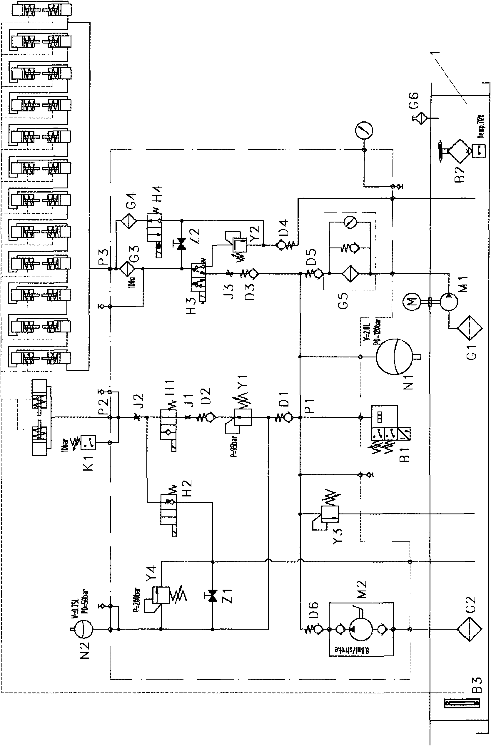
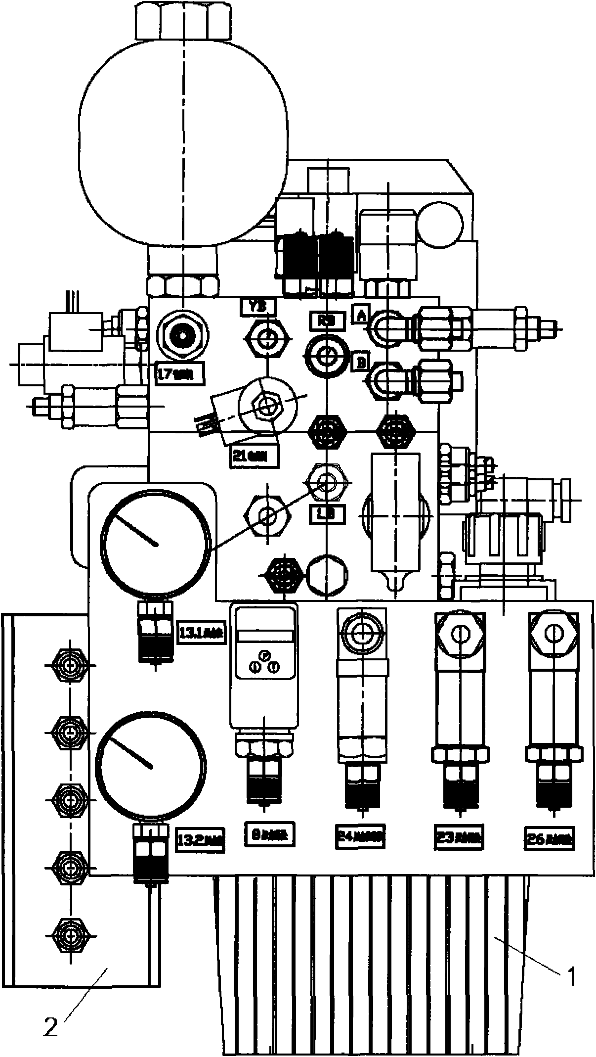
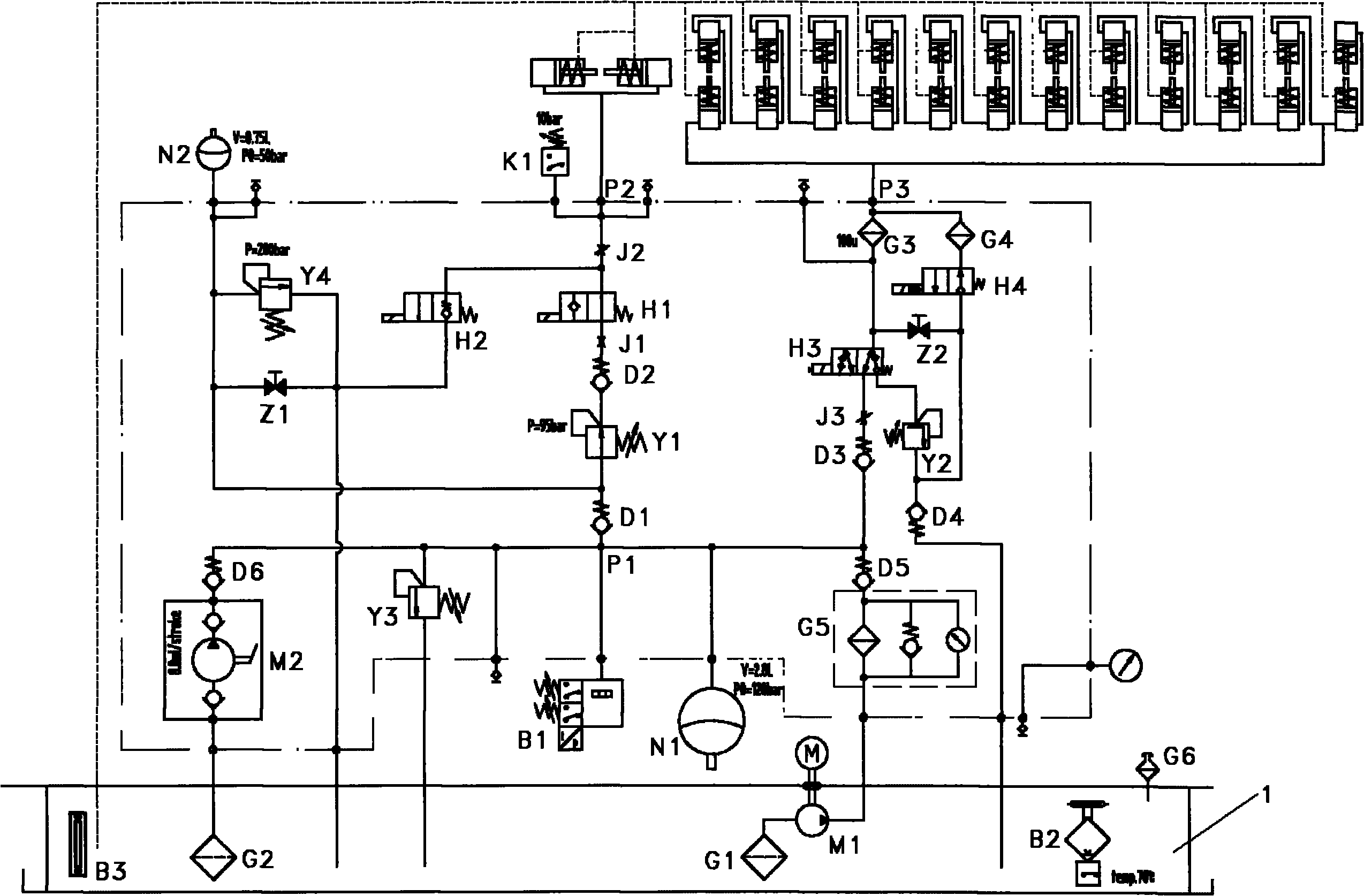
[0023] Such as Figure 1-Figure 2 As shown, a hydraulic braking system for a megawatt fan provided by the embodiment of the present invention includes: an oil tank 1, an electrical box 2, a motor pump M1, a manual pump M2, a main accumulator N1, and an auxiliary accumulator N2 and brake modules;

[0024] The oil tank 1 is equipped with hydraulic oil; the brake module is provided with an oil inlet P1, a spindle brake control interface P2 and a yaw brake control interface P3;

[0025] The oil inlet of the motor pump M1 is connected to the oil tank 1 through a filter G1 and immersed in hydraulic oil, and its oil outlet is connec...


PUM


Abstract

The invention discloses a hydraulic braking system for a megawatt fan, relates to the technical field of wind power generation and aims to solve the technical problems in the prior art. The system comprises an oil tank, an electric box, a motor pump, a manual pump, two accumulators and a brake module, wherein the motor pump and the manual pump are connected with an oil inlet of the brake module; the motor pump is a main power source and the manual pump is a standby power source; the two accumulators provide auxiliary power for the brake module; and a control oil circuit of the brake module isdivided into three paths, namely a first path starts from the oil inlet of the brake module to a spindle brake control interface of the brake module through a group of valves, and is a spindle brake control oil circuit, a second path starts from a secondary accumulator to a spindle brake control interface of the brake module through a group of valves, and is a spindle brake auxiliary control oil circuit, and a third path starts from the oil inlet of the brake module to a yaw brake control interface of the brake module through a group of valves, and is a yaw brake control oil circuit. The provided system can continuously work during power failure.

Description

technical field [0001] The invention relates to the technology of wind power generation, in particular to the technology of a hydraulic brake system of a megawatt fan. Background technique [0002] The main function of the hydraulic brake system of megawatt wind turbines is to provide power for the yaw brake actuator and the main shaft brake actuator. [0003] The hydraulic braking system of the existing megawatt fan has the following defects: 1) Since the motor pump is used as the power source of the brake actuator, when the system loses power or the motor pump fails, the brake actuator will lose the power source. 2) During the yaw braking process of the wind turbine, the existing system controls the oil supply flow and yaw pressure of the yaw brake to be unstable, so the stability and reliability of the wind turbine yaw brake Poor, uneven force on yaw power components, easy to be damaged due to fatigue impact; 3) The existing system needs to continue to use hydraulic oil ...

Claims


Application Information

Patent Timeline
Patent Type & Authority Applications(China)
IPC IPC(8): F03D11/00F16D65/20F16D65/18
CPCY02E10/72Y02E10/723Y02E10/722
Inventor 陈建华
Owner SHANGHAI HUIYI CONTROL SYST
Learn More