Magnetic fluid damping device

A technology of magnetic liquid and vibration damping device, applied in the direction of magnetic spring, spring/shock absorber, spring, etc., can solve the problem that the vibration damping method is difficult to meet the requirements, and achieve the effect of small acceleration, small displacement and low frequency

Inactive Publication Date: 2011-04-27
BEIJING JIAOTONG UNIV
View PDF8 Cites 91 Cited by
  • Summary
  • Abstract
  • Description
  • Claims
  • Application Information

AI Technical Summary

Problems solved by technology

Other vibration reduction methods are difficult to meet the requirements

Method used


Image

  • Magnetic fluid damping device
  • Magnetic fluid damping device
  • Magnetic fluid damping device

Examples


Embodiment approach 1

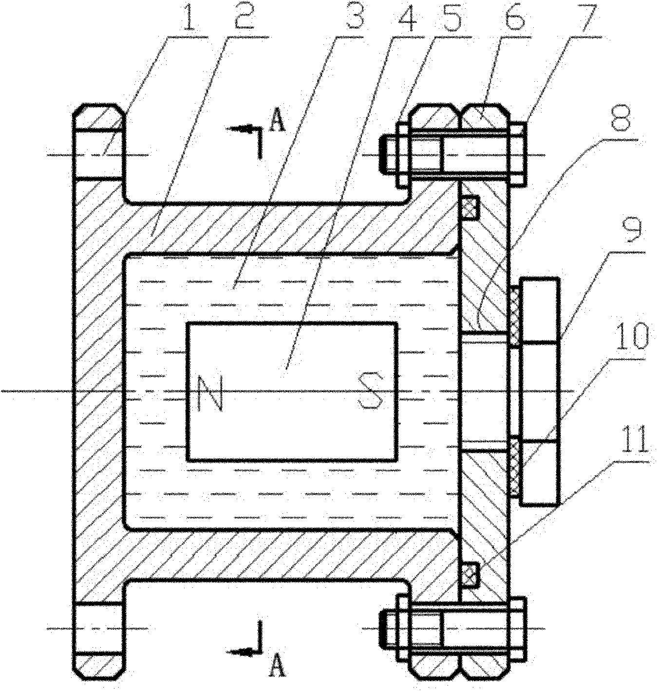
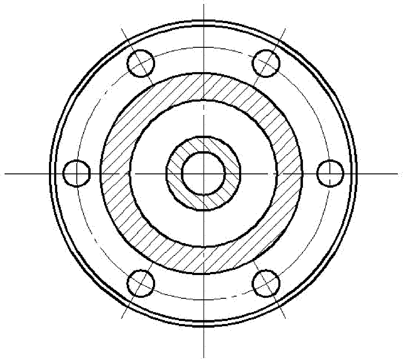
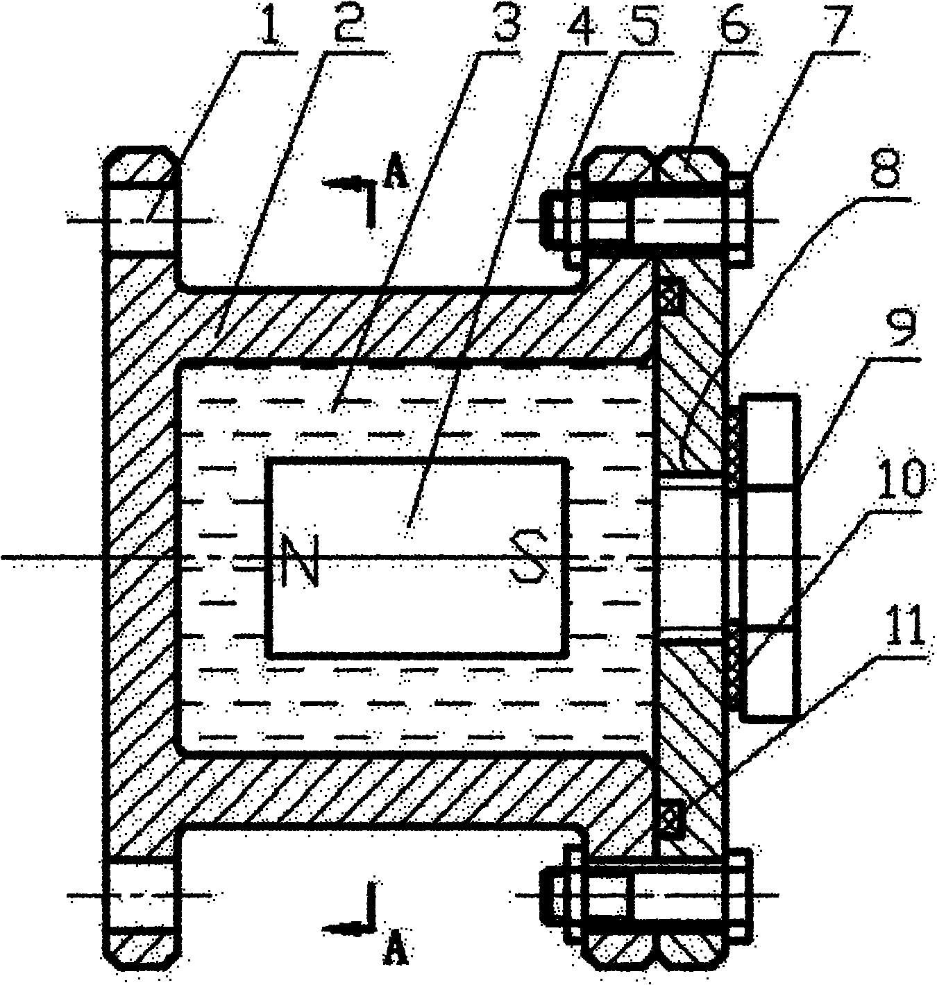
[0021] A magnetic liquid damping device, which is composed of a non-magnetic shell 2, a magnetic liquid 3, a permanent magnet 4, a nut 5, an end cover 6, a bolt 7, a screw 9, a gasket 10 and an O-ring 11.

[0022] Connections between the above parts:

[0023] Put the permanent magnet 4 into the cavity of the non-magnetic shell 2, and fix the end cover 6 with the O-ring 11 on one end of the non-magnetic shell 2 with the bolt 7 and the nut 5;

[0024] Fill the cavity of the non-magnetic shell 2 with magnetic liquid 3 through the threaded hole 8, and seal it with screws 9 and gaskets 10.

[0025] The shape of the permanent magnet 4 is a round tube, and its size parameters are: the ratio of the outer diameter of the round tube to the inner diameter of the non-magnetic shell 2 cavity is 0.5, the thickness of the round tube is 0.20mm, and the length is equal to the inner diameter of the non-magnetic shell 2. The length ratio is 0.25.

[0026] The magnetic liquid 3 is a diester-bas...

Embodiment approach 2

[0028] The difference between Embodiment 2 and Embodiment 1 is that the ratio of the outer diameter of the round tube to the inner diameter of the cavity of the non-magnetic shell 2 is 0.75, the thickness of the round tube is 0.35 mm, and the ratio of the length to the length of the non-magnetic shell 2 is 0.75.

[0029] The magnetic liquid 3 is water-based magnetic liquid.

Embodiment approach 3

[0031] The difference between Embodiment 3 and Embodiment 1 is that the ratio of the outer diameter of the round tube to the inner diameter of the cavity of the non-magnetic shell 2 is 0.6, the thickness of the round tube is 0.25 mm, and the ratio of the length to the length of the non-magnetic shell 2 is 0.5.

[0032] The magnetic liquid 3 is an oil-based magnetic liquid or a kerosene-based magnetic liquid.

[0033] The through hole 1 is designed for connection to the device to be damped.

[0034] The threaded hole 8 is designed to facilitate the injection of magnetic liquid.

[0035] The material of the screw 9, the non-magnetic shell 2 and the end cover 6 is 1Cr18Ni9Ti.

[0036] The permanent magnet 4 is made of NdFeB material.

[0037] The invention is suitable for local vibration reduction of many longer objects (such as solar sails, satellite antennas, etc.) in space vehicles.


PUM


Abstract

The invention relates to a magnetic fluid damping device, which is suitable for damping long objects in spacecrafts and solves the problem of the damping of the long objects in the spacecrafts. The device comprises a non-magnetic shell (2), magnetic liquid (3), a permanent magnet (4), a nut (5), an end cover (6), a bolt (7), a screw (9), a sealing gasket (10) and an O-shaped seal ring (11). The parts are connected in a way that: the permanent magnet (4) is arranged in the non-magnetic shell (2); the end cover (6) with the O-shaped seal ring (11) is fixed to one end of the non-magnetic shell (2) by the bolt (7) and the nut (5); the magnetic liquid (3) is filled into the non-magnetic shell (2) by a threaded hole (8); and the non-magnetic shell (2) is sealed by the screw (9) and the sealing gasket (10). The device is sensitive to inertia force, can perform damping on the vibration with the characteristics of low frequency, small displacement and low accelerated speed, and has long service life and simple assembly method.

Description

technical field [0001] The invention relates to a vibration damping structural member, which is suitable for vibration damping of long objects in spacecraft. Background technique [0002] Magnetic fluid damping is a new type of damping that is very sensitive to inertial forces. In the space vehicle, due to its special working environment and the limitations of energy, volume and weight, the shock absorber is required to be small in size, light in weight and high in reliability. In spacecraft, there are many local vibration reduction problems of long objects (such as solar panels, satellite antennas, etc.), and the vibration of these long objects has the characteristics of low frequency, small displacement, and small acceleration. For vibrations of this nature, the damper must be very sensitive to inertial forces. Other damping methods are difficult to meet the requirements. Contents of the invention [0003] The technical problem to be solved by the present invention is...

Claims


Application Information

Patent Timeline
Patent Type & Authority Applications(China)
IPC IPC(8): F16F6/00
Inventor 李德才王庆雷
Owner BEIJING JIAOTONG UNIV
Why Eureka
Try Eureka