
Burner

A burner and gas technology, applied in the direction of burners, gas fuel burners, combustion methods, etc., can solve the problems of mutual interference, easy backfire, blockage, etc., and achieve low emissions, improved combustion efficiency, and high power Effect

Active Publication Date: 2011-04-27
NINGBO FOTILE KITCHEN WARE CO LTD
View PDF6 Cites 10 Cited by
  • Summary
  • Abstract
  • Description
  • Claims
  • Application Information

AI Technical Summary

Problems solved by technology

And the current burner generally has multiple jet holes. When all the jet holes are ignited, multiple combustion flames will be formed. If the position of the jet holes is not designed properly, the flames will interfere with each other, which is easy to burn. Tempering occurs
And the air jet hole is directly exposed to the outside, and it is easy to be blocked by external dust and other sundries

Method used


Image

  • Burner
  • Burner
  • Burner

Examples


Embodiment Construction

[0020] The present invention will be further described in detail below in conjunction with the accompanying drawings and embodiments.

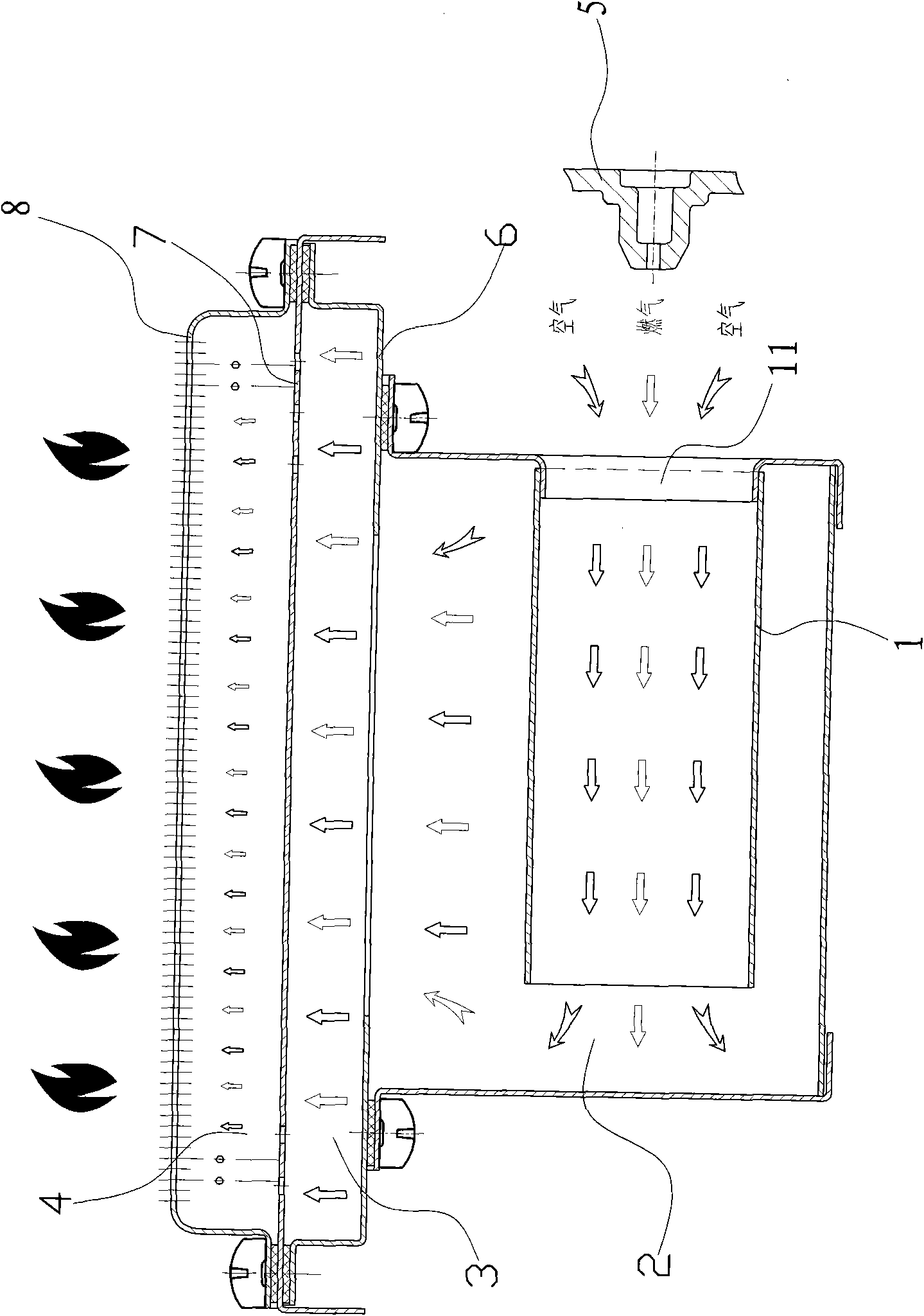
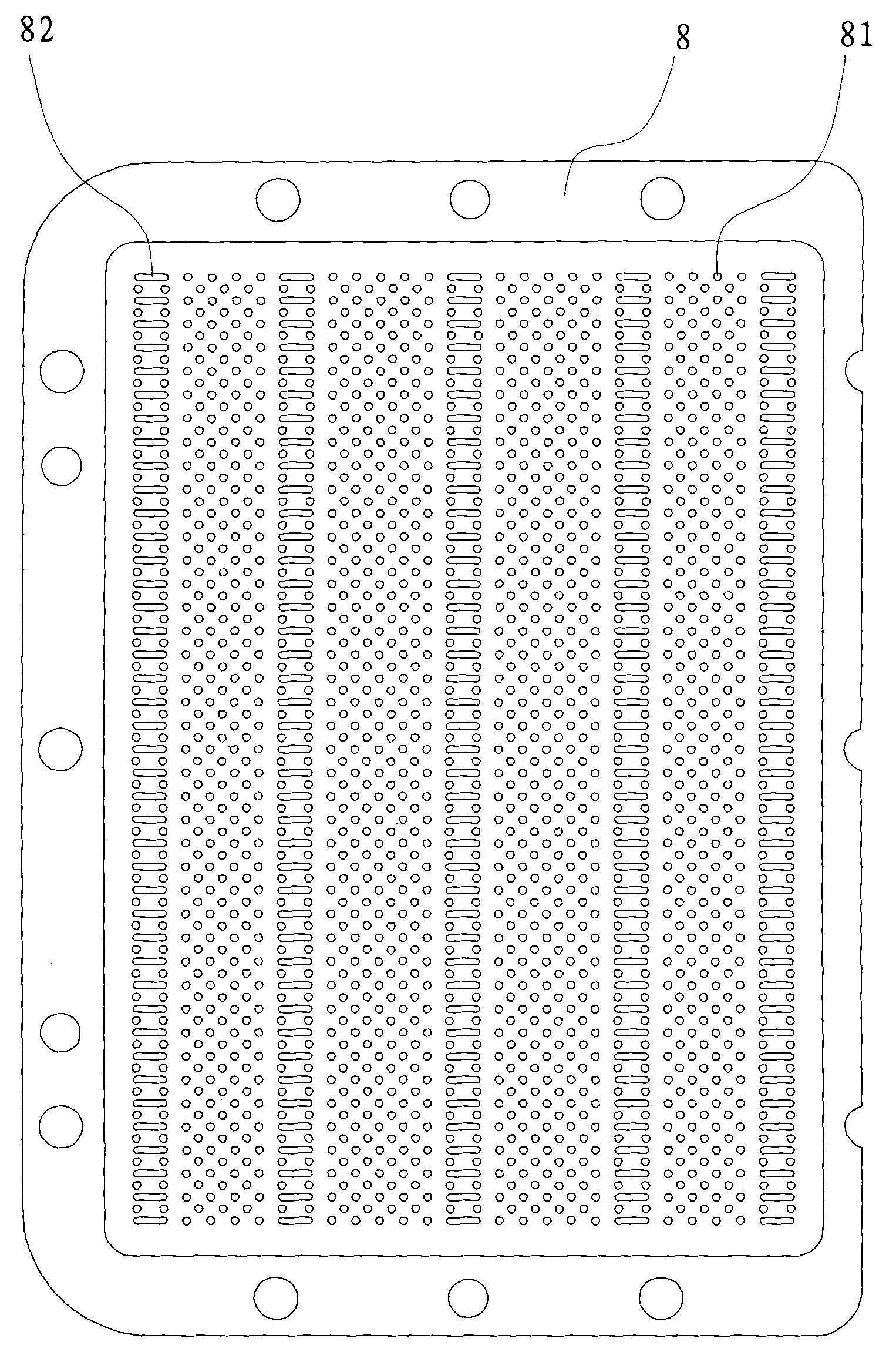
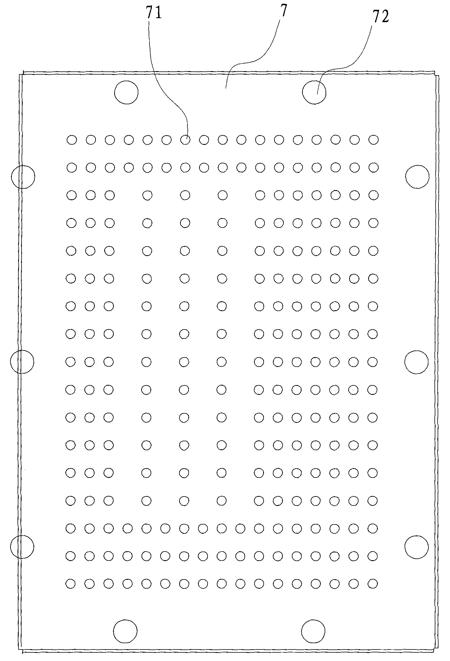
[0021] Such as figure 1 The shown burner includes a gas mixing chamber for mixing gas and air, and the gas mixing chamber includes a draft tube 1, a premixing chamber 2, a first mixing chamber 3 and a second mixing chamber 4, wherein the The air inlet 11 of the guide pipe 1 corresponds to the external nozzle 5, the air outlet of the guide pipe communicates with the premix chamber 2, and the first mixing chamber 3 is arranged in the premix chamber 2. The upper part, and separated by a baffle plate 6 with a middle opening 61, the second mixing chamber 4 is arranged on the upper part of the first mixing chamber 3, and separated by a flow plate 7, the flow plate 7 There are a plurality of air outlet holes 71 with a diameter of 2 mm distributed on the top, and there are mounting screw holes 72 around the flow equalizer. The top of the second mixin...


PUM


Abstract

The invention relates to a burner, which comprises a gas mixing chamber for mixing gas and air, and is characterized in that: a cover plate is detachably arranged on the top of the gas mixing chamber; and a plurality of fire holes which allow flame to pass through are distributed on the cover plate at intervals. Compared with the prior art, the burner has the advantages that: the cover plate is arranged on the top of the gas mixing chamber, is provided with the fire holes and can effectively buffer the pressure of the flame jetted from jet orifices, so that floating flame is formed on the surface of the cover plate; and the whole burner is difficult to temper.

Description

technical field [0001] The invention relates to a burner for a gas water heater or a gas stove. Background technique [0002] Existing burners for gas water heaters or gas stoves generally include a mixing chamber for mixing air and gas. Gas and air inlet holes are arranged on the mixing chamber, and the inlet holes correspond to nozzles. Inject into the mixing chamber, when the gas is injected into the mixing chamber, it also brings the external air into the mixing chamber. In the mixing chamber, the air and the gas are fully mixed, and an air injection hole is set on the top of the mixing chamber. The gas injection hole communicates with the inner space of the mixing chamber, and an ignition assembly is generally arranged next to the injection hole. When the ignition assembly is ignited, the mixture of gas and air in the mixing chamber is ejected from the injection hole under high pressure to achieve ignition. At this time, after the mixture of gas and air sprayed directl...

Claims


Application Information

Patent Timeline
Patent Type & Authority Applications(China)
IPC IPC(8): F23D14/02F23D14/62F23D14/82F23D14/84
Inventor 周高云卢志龙徐德明茅忠群诸永定
Owner NINGBO FOTILE KITCHEN WARE CO LTD
Learn More