
Circumferentially graded low-pollution combustion chamber with multiple middle spiral-flow flame stabilizing stages

A combustion chamber and intermediate stage technology, which is applied in the field of circumferentially graded low-polluting combustion chambers, can solve the problems of lean oil and unstable combustion in the main combustion area of ​​the combustion chamber.

Inactive Publication Date: 2011-04-27
BEIHANG UNIV
View PDF20 Cites 54 Cited by
  • Summary
  • Abstract
  • Description
  • Claims
  • Application Information

AI Technical Summary

Problems solved by technology

However, in order to meet the increasingly stringent emission standards of aero-engine pollutants in the future, it is inevitable that the main combustion area of ​​the combustion chamber will be leaner, and the combustion chamber designer will encounter combustion instability more and more frequently.
In addition, the topic of combustion instability is also a hot spot in the field of low-pollution combustor design.

Method used


Image

  • Circumferentially graded low-pollution combustion chamber with multiple middle spiral-flow flame stabilizing stages
  • Circumferentially graded low-pollution combustion chamber with multiple middle spiral-flow flame stabilizing stages
  • Circumferentially graded low-pollution combustion chamber with multiple middle spiral-flow flame stabilizing stages

Examples


Embodiment Construction

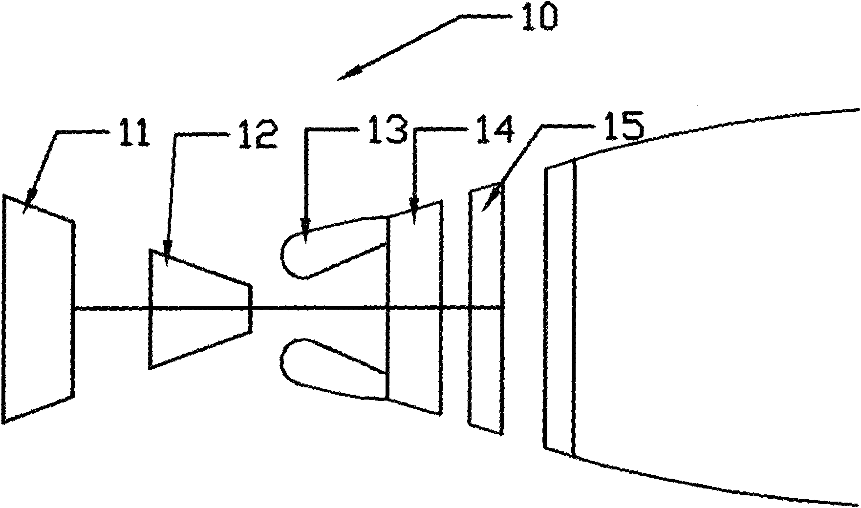
[0036] figure 1 is a schematic diagram of the engine 10 . Engine 10 includes a low-pressure compressor 11 , a high-pressure compressor 12 , a combustion chamber 13 , a high-pressure turbine 14 and a low-pressure turbine 15 . When the engine 10 is working, the air enters the high-pressure compressor 12 after being compressed by the low-pressure compressor 11, and the high-pressure air enters the combustion chamber 13 of the present invention to burn, and the fuel injection system injects fuel into the high-pressure airflow, and the fuel injection system in the combustion chamber 13 is fully and effectively burned, and the high-temperature and high-pressure gas formed enters the high-pressure turbine 14 and the low-pressure turbine 15, thereby pushing the turbines to do work.

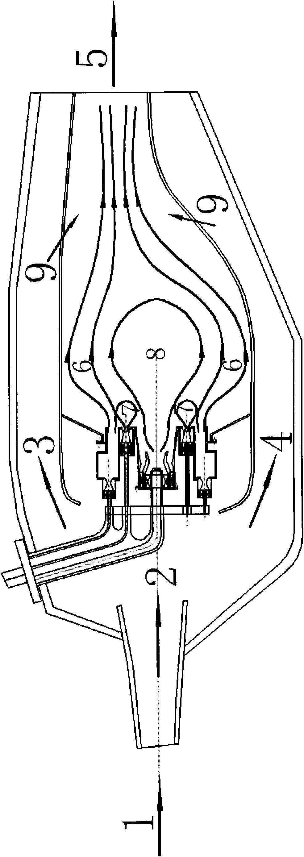
[0037] figure 2 It is a working schematic diagram of a circumferentially graded low-pollution combustion chamber with multi-swirl intermediate flame-stabilizing stages designed by the present invention...


PUM


Abstract

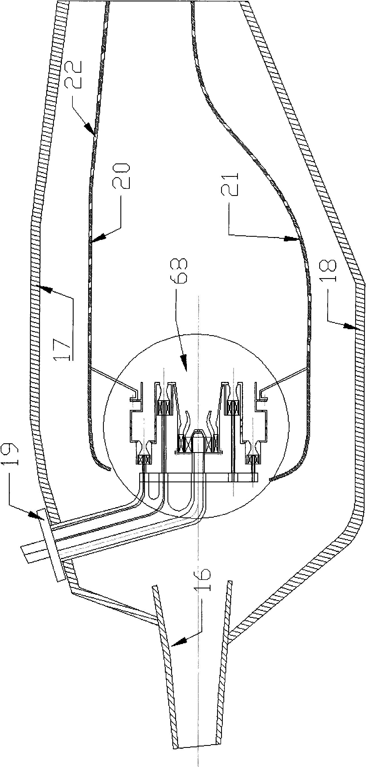
The invention discloses a circumferentially graded low-pollution combustion chamber with multiple middle spiral-flow flame stabilizing stages. The combustion chamber has a single annular cavity structure; a low-pollution combustion organization mode in which air grading is matched with fuel oil grading is adopted; all fuel gas is supplied by a duty stage, a middle stage and a main combustion stage; and fuel oil grading supply proportion is controlled accurately according to the operating condition of an engine and the requirement on stable low-pollution combustion. The duty stage has a combined structure in which two-stage axial spiral flow is matched with a venturi tube, and a formed low-speed reflux region can support stable combustion of the combustion chamber; the middle stage has a combined structure in which a plurality of single-stage axial spiral flow circumferentially and uniformly distributed on the same circumference in the same axial cross section are matched with the venturi tube, and a formed middle flame stabilizing stage combustion region is used for intensifying and stabilizing flame in the main combustion stage; and the main combustion stage has a combined structure in which a plurality of single-stage axial spiral flow circumferentially and uniformly distributed on the same circumference in the same axial cross section are matched with the venturi tube, so that an oil and gas mixed poor-oil premixing and pre-evaporation combustion mode is intensified and the emission of pollutants is further reduced greatly.

Description

technical field [0001] The invention relates to a low-pollution combustion chamber of an aero-engine, in particular to a circumferentially graded low-pollution combustion chamber with multi-swirl intermediate flame-stabilizing stages. Combustion stability of the combustion chamber adopting this scheme is greatly improved, and pollutant emission can be significantly reduced at the same time. Background technique [0002] Civil aviation engines are increasingly subject to stricter pollutant emission standards. The currently adopted CAEP6 standard stipulates that civil aeroengine NO X Emissions are 60% lower than the average level of emissions from engines currently in service. The emission standards for industrial gas turbines are more stringent, requiring emission concentrations of one part per million. The increasingly stringent pollutant discharge standards are also prompting people to further explore more effective low-pollution combustion organization forms. [0003] ...

Claims


Application Information

Patent Timeline
IPC IPC(8): F23R3/58F23R3/20F23R3/30
Inventor 李锋张珊珊孙佰刚杨晖张莉涓
Owner BEIHANG UNIV
Learn More