Eureka AIR delivers breakthrough ideas for toughest innovation challenges, trusted by R&D personnel around the world.

System and method for compensating flow heat loss by utilizing additional heat generated through flow microbubble cavitation in focused ultrasound field

A technology of focused ultrasound and heat compensation, applied in the field of focused ultrasound, can solve the problems of increased pain, increased risk, high temperature, etc., and achieve the effect of enhancing reflection and improving the efficiency of ultrasonic heating

Inactive Publication Date: 2011-05-11
XI AN JIAOTONG UNIV
View PDF3 Cites 2 Cited by
  • Summary
  • Abstract
  • Description
  • Claims
  • Application Information

AI Technical Summary

Problems solved by technology

Increasing the single ultrasonic power or action time can increase the temperature of the target area, but at the same time, the temperature of the normal tissue on the ultrasonic propagation path and the surrounding target area will be too high, resulting in toxic side effects
In addition, the effect of heat removal by flow can be reduced by means of blocking blood supply and injecting iodized oil, but such invasive methods increase human suffering and risk

Method used


Image

  • System and method for compensating flow heat loss by utilizing additional heat generated through flow microbubble cavitation in focused ultrasound field
  • System and method for compensating flow heat loss by utilizing additional heat generated through flow microbubble cavitation in focused ultrasound field
  • System and method for compensating flow heat loss by utilizing additional heat generated through flow microbubble cavitation in focused ultrasound field

Examples


Embodiment 1

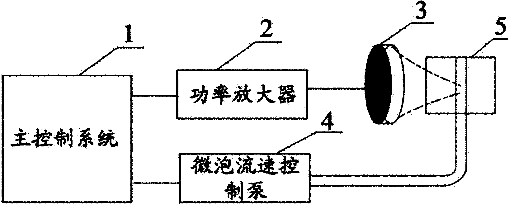
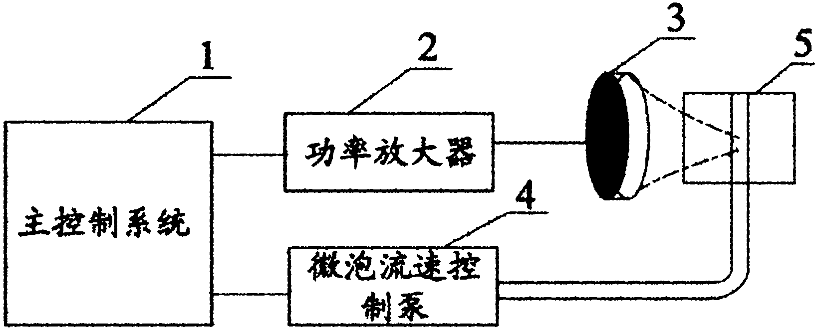
[0012] Embodiment 1: A system that uses flow microbubble cavitation to generate additional heat to compensate flow heat loss in a focused ultrasonic field, such as figure 1 shown. Including: main control system 1, power amplifier 2, focused ultrasonic transducer 3, microbubble flow rate control pump 4, sample 5.

[0013] System connection: the main control system 1 is connected to the power amplifier 2 and the microbubble flow rate control pump 4, the power amplifier 2 is connected to the focused ultrasound transducer 3, and the microbubble flow rate control pump 4 controls the flow rate of the microbubble solution in the simulated body.

[0014] The system consists of two parts, namely the focused ultrasound part and the microbubble flow rate control part. The focused ultrasound part includes a focused ultrasound transducer and a power amplifier. The ultrasonic power amplifier with continuously adjustable frequency, power and action time drives the single-array concave sphe...

Embodiment 2

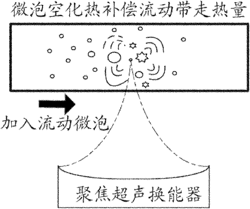
[0015] Embodiment 2: A method of using flow microbubble cavitation to generate additional heat to compensate the heat taken away by the fluid in a focused ultrasonic field, such as figure 2 shown.

[0016] In microbubble-assisted focused ultrasound hyperthermia, a transparent tissue imitation phantom through which microbubble solution can flow is used. The pipeline in the phantom is perpendicular to the sound axis of ultrasound treatment, and the focus of ultrasound treatment is adjusted in the pipeline by a three-dimensional moving device. The microbubble solution is injected into the pipeline, and the flow rate is controlled by the microbubble flow rate control pump. Afterwards, the focused ultrasound focal region is used to act on the target area, and the microbubble ultrasonic cavitation synergistic mechanism is used to generate additional heat, thereby compensating for the heat taken away by the flow and promoting the temperature increase near the pipeline.


PUM


Abstract

The invention discloses a system and method for compensating flow heat loss by utilizing additional heat generated through flow microbubble cavitation in a focused ultrasound field. When focused ultrasound acts on a local medium containing flow liquid, microbubble is injected into the medium and arrives at the focused ultrasound field following the flow liquid. Under the action of the focused ultrasound, the additional heat generated by utilizing a flow microbubble cavitation synergistic mechanism is used for compensating the heat carried away by the flow liquid, thereby promoting the rising of the temperature of the local medium nearby a pipeline. The system comprises a main control system, a power amplifier, a focused ultrasonic transducer and a microbubble flow velocity control pump. In the invention, transient physics of the flow microbubble, such as cavitation and the like, occur under the action of ultrasound and the effects of reflection, scattering and the like on the ultrasound are enhanced; the additional heat generated by utilizing the flow microbubble cavitation synergistic mechanism can be used for compensating the heat carried away by the flow, thereby enhancing the heating efficiency of the ultrasound.

Description

Technical field: [0001] The invention belongs to the field of focused ultrasound, and in particular relates to a system and method for compensating the heat taken away by flow by utilizing the additional heat generated by cavitation of flow microbubbles in a focused ultrasound field. Background technique: [0002] When ultrasound propagates in the medium, part of the ultrasonic energy is absorbed by the medium and converted into heat energy, which causes the temperature of the medium to rise. Utilizing the advantages of focused ultrasound in vitro focusing, rapid, and local heating, especially the use of high-intensity focused ultrasound, encouraging pioneering results have been achieved in clinical tumor hyperthermia. However, this focused ultrasound local heating technology still has problems such as low efficiency and long time to be solved. Due to heat conduction, especially when the medium contains a lot of flowing liquid, the heat taken away by the flow hinders the in...

Claims


Application Information

Patent Timeline
Patent Type & Authority Applications(China)
IPC IPC(8): A61N7/02
Inventor 张思远周凡渝万明习丁婷符权有杨旭王素品
Owner XI AN JIAOTONG UNIV
Why Eureka
Eureka Blog
Learn More