Design method for hob of cylindrical gear

A technology of cylindrical gear and design method, which is applied in the direction of gear tooth manufacturing tools, gear tooth manufacturing devices, and components with teeth, etc., which can solve the problems of difficult design, low machining accuracy, and difficult calculation, etc., and achieve convenient computer programming , The tooth shape is smooth and smooth, and the gear hobbing process is simple

Active Publication Date: 2011-05-11
CHINA HANGFA GUIZHOU LIYANG AVIATION POWER CO LTD
View PDF0 Cites 10 Cited by
  • Summary
  • Abstract
  • Description
  • Claims
  • Application Information

AI Technical Summary

Problems solved by technology

The main factors affecting the service life of timing gears and belts are unreasonable tooth shape design and low machining accuracy.
In order to improve the machining accuracy of the timing gear, it is necessary to accurately design the hobbing cutter, but since the timing gear drawings generally give discrete point coordinates, the design is difficult and the calculation is difficult
At present, the approximate machining tooth shape is generally used to replace the design tooth shape in the current technology. The approximate tooth shape deviates from the design tooth shape and the accuracy is poor.
Another widely used method is powder metallurgy molding or precision casting, etc., but its manufacturing cost is high, and the gear precision is difficult to meet the design requirements.

Method used


Image

  • Design method for hob of cylindrical gear
  • Design method for hob of cylindrical gear
  • Design method for hob of cylindrical gear

Examples


Embodiment Construction

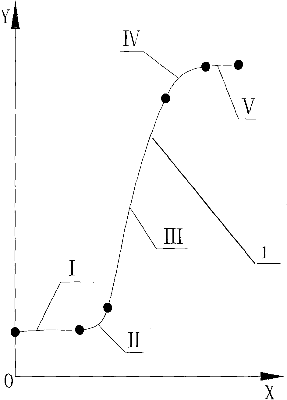
[0030] Such as figure 1 As shown, we first roughly segment the tooth shape point coordinates (1) given by the gear in the drawing, which can generally be divided into five curves: I, II, III, IV, V.

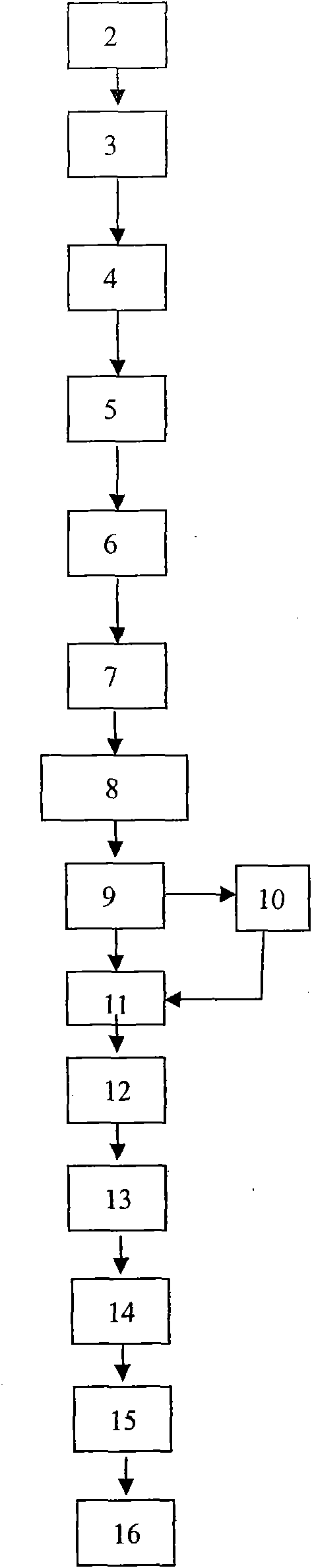
[0031] Such as figure 2 As shown, it is determined step by step according to the steps of the design flow chart figure 1 The coordinate points that should be included in each segment on the given tooth profile point coordinates (1) of the middle gear, that is, determine the decomposition points of each segment; at the same time, design the tooth profile of the hob cutter that processes each segment of tooth profile according to the steps point coordinates.

[0032] figure 1 Section I mentioned in the above is the set of points on the gear dedendum circle, section II is the set of points on the transition curve of the dedendum, section III is the set of working points, section IV is the set of point transition arc points on the tooth tip, and section V is the set of points on ...


PUM


Abstract

The invention relates to a design method for a hob of a cylindrical gear, in particular to a design method for a hob of a timing gear of an automobile engine. The coordinate point of a tooth form of the hob is obtained by machining the given coordinate point of a tooth form of the cylindrical gear. The hob designed by the method can machine all given coordinate points on the tooth form of the cylindrical gear, the machined tooth form is smooth, and singular points do not protrude, so that the quality of a cylindrical gear product is improved.

Description

technical field [0001] The invention relates to a design method of a cylindrical gear hobbing cutter, in particular to a design method of a timing gear hobbing cutter of an automobile engine. Background technique [0002] There are many kinds of gear transmission parts, which can be divided into involutes, cycloids, arcs and various modification curves from the tooth shape; from the transmission mode, they can be divided into cylindrical gears, bevel gears, worm gears, etc.; The processing technology is also constantly improving, mainly including gear hobbing, gear shaping, powder metallurgy molding, precision casting, etc. For cylindrical gears, hobbing cutters are generally used to process the tooth shape (the process name is hobbing), and finally shaving or grinding are used to refine the tooth shape. The accuracy of hobbing directly affects the final quality of cylindrical gears. [0003] For the timing gear, due to the particularity of its tooth shape parameters, it is...

Claims


Application Information

Patent Timeline
Patent Type & Authority Applications(China)
IPC IPC(8): B23F21/16
Inventor 王攀
Owner CHINA HANGFA GUIZHOU LIYANG AVIATION POWER CO LTD
Why Eureka
Try Eureka