Device for cooling an exhaust gas stream

A technology of exhaust gas flow and exhaust pipe, which is applied in the direction of exhaust device, noise reduction device, exhaust treatment, etc., can solve the problem of increased exhaust gas back pressure, and achieve the effect of simple structure, space saving and avoiding blockage

Inactive Publication Date: 2011-05-11
DEERE & CO
View PDF5 Cites 6 Cited by
  • Summary
  • Abstract
  • Description
  • Claims
  • Application Information

AI Technical Summary

Problems solved by technology

However, the tapered shape of the nozzle or of the diverter housing in the direction of the exhaust gas flow leads to an undesired increase in the exhaust gas backpressure in the exhaust system.

Method used


Image

  • Device for cooling an exhaust gas stream
  • Device for cooling an exhaust gas stream
  • Device for cooling an exhaust gas stream

Examples


Embodiment Construction

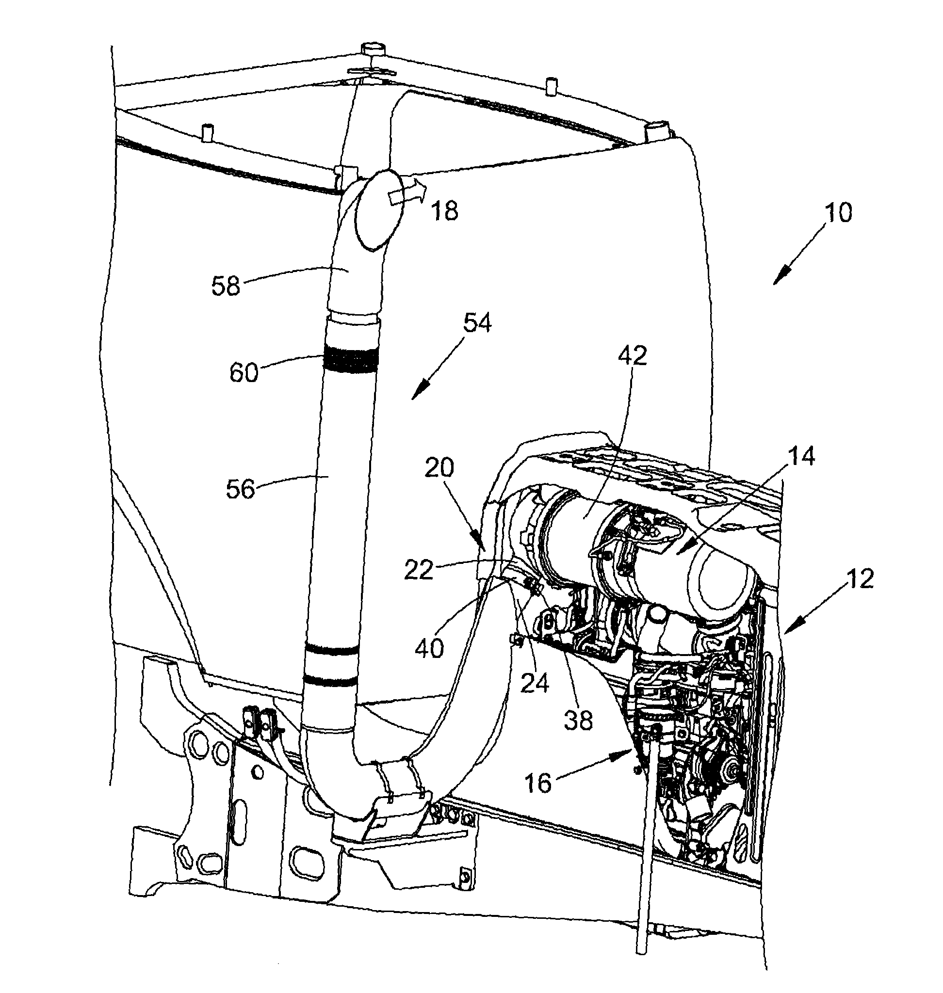
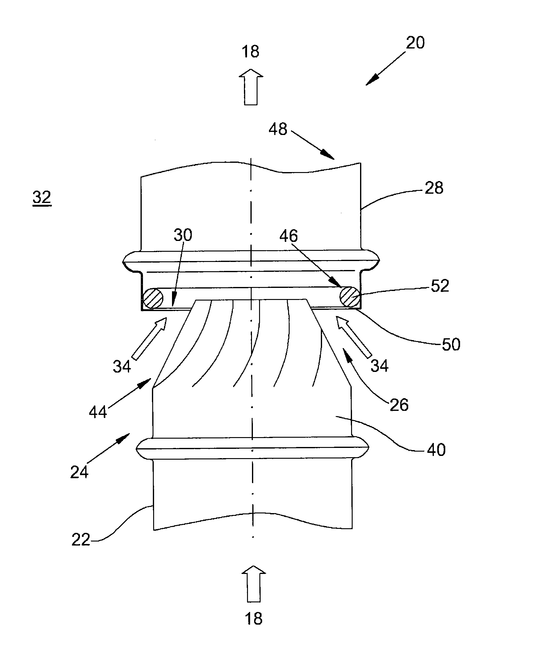
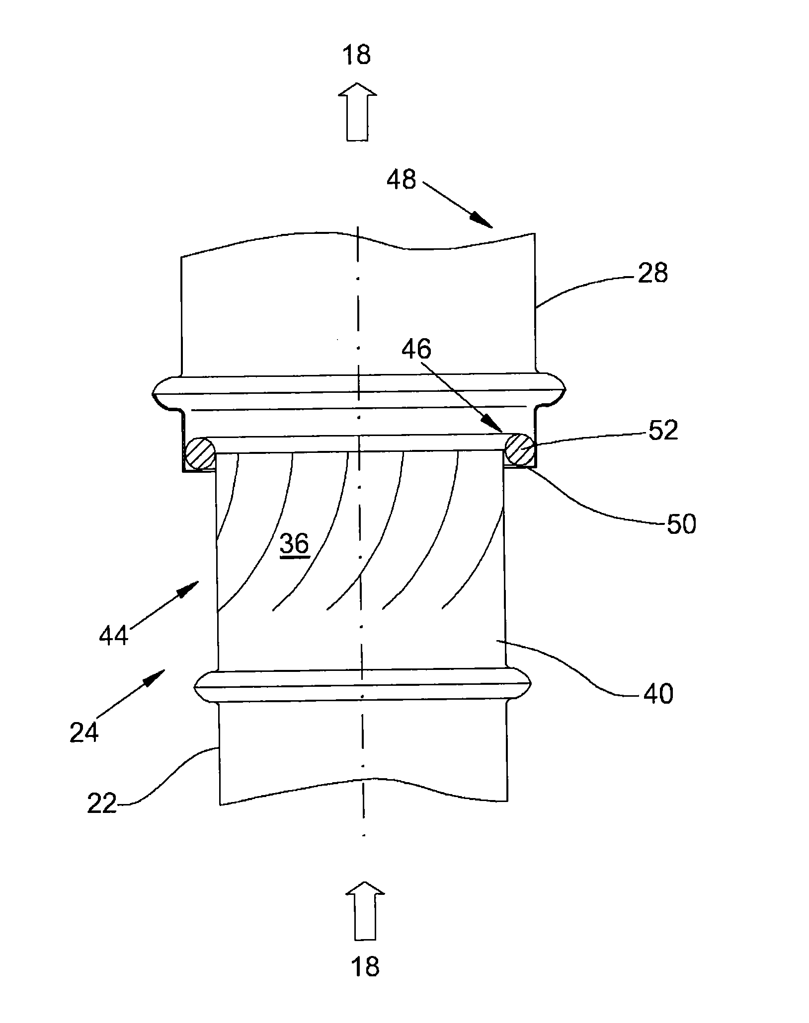
[0022] figure 1 Shows a general perspective view of an embodiment of the device according to the invention for cooling the exhaust gas flow coming out of the soot particle filter on an agricultural production vehicle, wherein figure 2 Or image 3 During the regeneration phase of the carbon black particle filter or in other words outside the regeneration phase of the carbon black particle filter, the operation of the device according to the invention is reproduced. figure 1 A detailed view of the example shown in .

[0023] An agricultural production vehicle 10 configured, for example, as a tractor, includes a soot particulate filter 14 disposed in the engine compartment 12, wherein the soot particulate filter is configured as a conventional wall-flow filter, wherein the diesel engine of the agricultural production vehicle 10 16 Generated engine exhaust passes through porous filter walls made of ceramic or metallic material. Here, the soot particles contained in the engine ...


PUM


Abstract

An assembly for cooling an exhaust gas stream includes an outlet nozzle capable of being loaded by the exhaust gas stream. The outlet nozzle projects into an open end of an adjacent exhaust gas pipe so that a reduced pressure relative to the surrounding environment is produced in a suction region between the outlet nozzle and the exhaust gas pipe by flow of exhaust gas. Adjusting members vary the flow cross section of the outlet nozzle.

Description

technical field [0001] The invention relates to a device for cooling an exhaust gas flow, which has an outlet nozzle which can be acted upon by means of the exhaust gas flow and which protrudes into the open end of an adjoining exhaust gas pipe in such a way that between the outlet nozzle and the exhaust gas pipe In the suction region formed in between, a low pressure relative to the surroundings can be generated when the exhaust gas flows through. Background technique [0002] The emission standards published by the European Union gradually reduce the soot particles produced by diesel engines and emitted into the environment with the engine exhaust. The limitation of the emission of soot particles is achieved by using soot particle filters, usually so-called wall-flow filters, in which the engine exhaust gas passes through a porous filter wall made of ceramic or metallic material. Here, the soot particles contained in the engine exhaust gas deposit not only on the surface ...

Claims


Application Information

Patent Timeline
Patent Type & Authority Applications(China)
IPC IPC(8): F01N13/08F01N3/05
CPCF01N13/082F01N2270/02F01N2590/08
Inventor M.朗R.布鲁内特
Owner DEERE & CO
Why Eureka
Try Eureka