Method for improving data processing of absorption loss measurement of optical elements

A technology for optical components and data processing, which is applied in optical instrument testing, measuring devices, testing optical performance, etc., and can solve problems such as large absorption loss measurement errors.

Inactive Publication Date: 2011-05-11
INST OF OPTICS & ELECTRONICS - CHINESE ACAD OF SCI
View PDF2 Cites 10 Cited by
  • Summary
  • Abstract
  • Description
  • Claims
  • Application Information

AI Technical Summary

Problems solved by technology

Numerical calculation results show that for optical components with small thermal conductivity and non-25mm diameter, fixing the temperature sensor at 7mm will introduce a large measurement error of absorption loss

Method used


Image

  • Method for improving data processing of absorption loss measurement of optical elements
  • Method for improving data processing of absorption loss measurement of optical elements
  • Method for improving data processing of absorption loss measurement of optical elements

Examples


Embodiment Construction

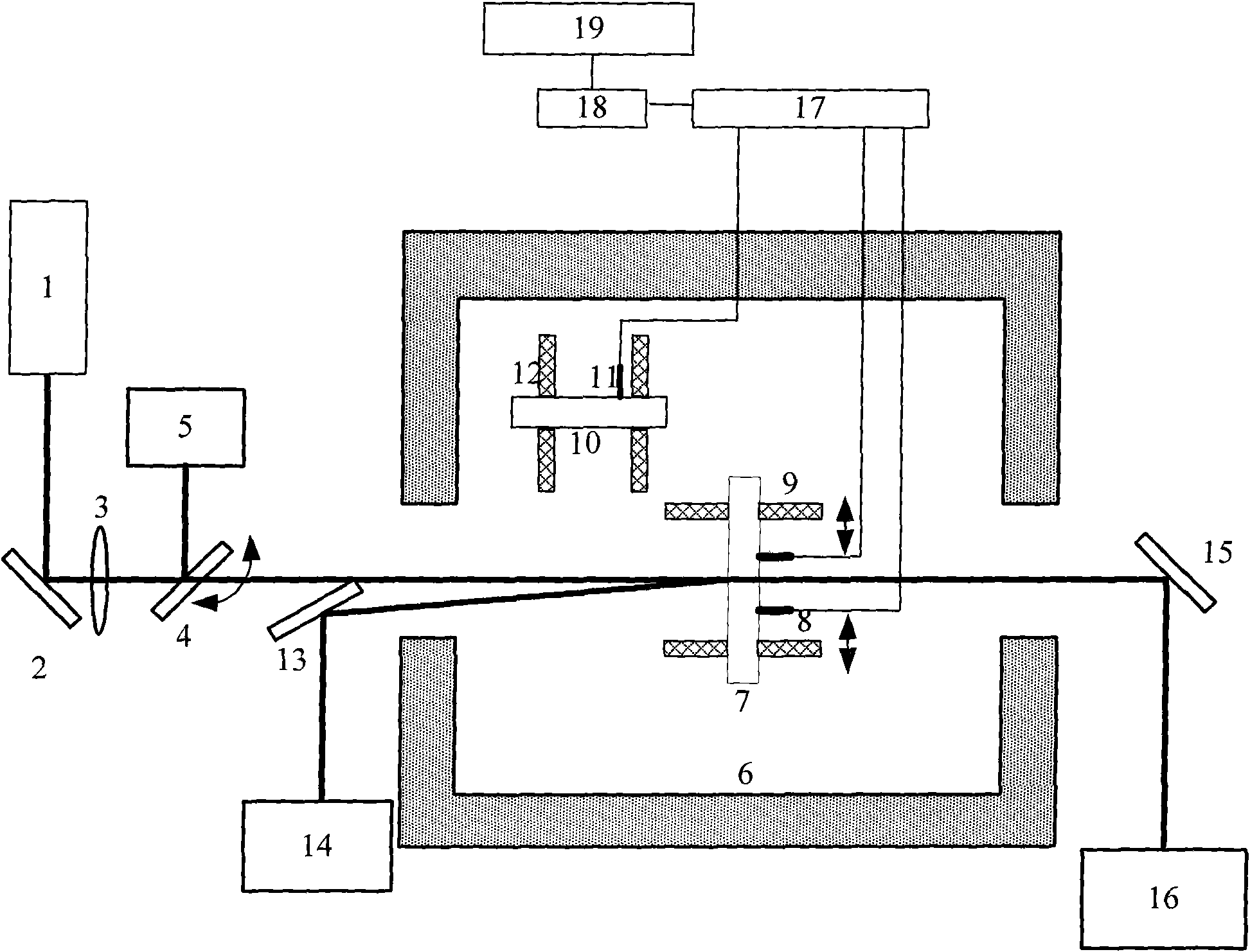
[0048] Attached below figure 1 The implementation process of the present invention is described in detail. like figure 1 As shown, the laser calorimetric absorption loss measurement of the present invention consists of a heating laser light source 1, a reflector 2, a focusing lens 3, an electric optical shutter 4, a power meter 5, an adiabatic sample chamber 6, an optical element to be measured 7, and an optical element to be measured Temperature sensor 8, optical element holder to be tested 9, reference optical element 10, reference optical element temperature sensor 11, reference optical element holder 12, reflector 13, light absorber 14, reflector 15, light absorber 16, bridge amplifier circuit 17, A / D converter 18 and computer 19. The thick line represents the optical path, and the thin line represents the signal connection line.

[0049] The laser beam output by the heating laser light source 1 passes through the 45-degree reflector 2 to bend the optical path, and afte...


PUM

PropertyMeasurementUnit
thicknessaaaaaaaaaa

Abstract

The invention discloses a method for improving the data processing of the absorption loss measurement of optical elements. The method comprises the steps of: continuously irradiating the surfaces of the optical elements with excitation beams which are focused through a lens, wherein the interior temperature of the optical elements rises up because of absorbing the energy of incident laser beams; establishing an accurate temperature model which can better reflect the physical reality of the optical elements; based on the accurate temperature model, obtaining an optimum temperature detection position different from that adopted by an international standard ISO11551 through carrying out numerical simulation on the temperature rise at different positions of the optical elements with a certain size and different thermal physical properties; adjusting a temperature sensor to the optimum temperature detection position to measure the temperature data on the surfaces of the optical elements; and obtaining the absorption loss values of samples by fitting the measured temperature data to a uniform temperature model adopted by the international standard ISO11551. Compared with a fixed temperature detection position adopted by the traditional international standard ISO11551, aiming at the sizes and thermal physical parameters of different optical elements to be measured, the method adopts the temperature sensor of which the position is adjustable to realize the purpose of more accurately measuring the absorption losses of the optical elements.

Description

technical field [0001] The invention relates to the field of optical element testing, in particular to an improvement and optimization method for data processing in laser calorimetric technology used for optical element absorption loss measurement. Background technique [0002] In large-scale lasers and their application systems, a large number of thin-film optical components, especially reflective optical components, are used. Due to the existence of thin-film absorption, the internal temperature of thin-film optical components rises due to laser beam irradiation during use, resulting in thermal distortion on the surface of optical components, and in severe cases, catastrophic damage to optical components will occur. Absorption loss directly determines the damage threshold of optical components, which limits the power or energy that can be carried by lasers and laser systems. At the same time, the thermal deformation of the surface of optical components due to absorption lo...

Claims


Application Information

Patent Timeline
Patent Type & Authority Applications(China)
IPC IPC(8): G01M11/00G01M11/02G01N25/20
Inventor 李斌成王艳茹高卫东
Owner INST OF OPTICS & ELECTRONICS - CHINESE ACAD OF SCI
Why Eureka
Try Eureka