
Method for on-site measuring permeability coefficient of landfill gas

A gas permeation and on-site measurement technology, applied in the field of resources and environment, can solve the problems of easy explosion, high risk, difficult to popularize, etc., and achieve the effects of convenient operation, high measurement accuracy and simple system

Inactive Publication Date: 2011-05-11
TSINGHUA UNIV
View PDF0 Cites 21 Cited by
  • Summary
  • Abstract
  • Description
  • Claims
  • Application Information

AI Technical Summary

Problems solved by technology

However, there is still relatively little data on the gas permeability coefficient of landfill piles, and the data are closely related to site conditions (landfill structure, landfill age, garbage type, and water content, etc.), and on-site measurement is urgently needed
[0006] At present, there is no report on the on-site measurement method and research of landfill gas permeability coefficient in China, and only Rasmussen (1993), Massmann (1994), Cestaro (2003) and P.Jain (2005) in foreign countries use compressed air injection. The method measures the pressure and air extraction flow under a certain flow rate, and uses the model to calculate the gas permeability coefficient of the landfill pile. However, when the concentration of methane after mixing air and landfill gas is 5-15%, it is very easy to explode, which is dangerous. High, so it is difficult to promote in the actual landfill

Method used


Image

  • Method for on-site measuring permeability coefficient of landfill gas
  • Method for on-site measuring permeability coefficient of landfill gas
  • Method for on-site measuring permeability coefficient of landfill gas

Examples


Embodiment Construction

[0030] The present invention will be described in further detail below in conjunction with the accompanying drawings and specific embodiments.

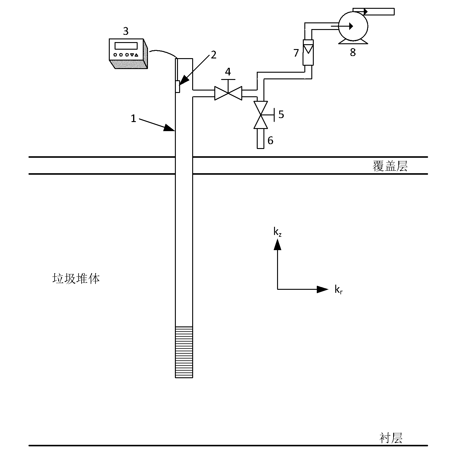
[0031] figure 1 It is a schematic structural diagram of a system for on-site measurement of landfill gas permeability coefficient provided by the present invention. The measuring system that this method adopts comprises lower opening tube well 1, gas pressure sensor 2, gas pressure display recorder 3, air extraction pipeline valve 4, gas flow meter 7 and centrifugal fan 8; Described gas pressure sensor 2 is installed in the tube well The upper part is connected with the gas pressure display recorder through the data line; the centrifugal fan is communicated with the upper end of the tube well through the gas pipeline, and the gas extraction pipeline valve and the gas flow meter are installed on the gas pipeline; A leachate venting pipe 6 and a leachate venting valve 5 are also installed on the gas pipeline between the exhaust pipe va...


PUM

PropertyMeasurementUnit
Diameteraaaaaaaaaa

Abstract

A method for on-site measuring permeability coefficient of landfill gas adopts a measurement system comprising a lower opened tube well, a gas pressure sensor, a gas pressure display recording instrument, an extraction pipeline valve, a leachate emptying valve, a leachate emptying pipe, a gas measuring apparatus and a centrifugal fan. The method adopting extraction mode comprises the following step tube well internal pressure and extraction flow rate are recorded after the gas is stable; and the permeability coefficient of landfill gas is obtained after the substitution to a stationary model. In the method, not only are the conventional extraction pipeline and equipment in a landfill utilized, but also the defects of easy explosion and high hazards which are caused after air and methane are mixed when gas injection mode is adopted are overcome, further the characteristics of landfill covering permeability and permeability coefficient difference in horizontal direction and vertical direction of the landfill caused by layered landfilling and compaction are fully considered. Therefore, the method provided by the invention has the advantages of high measurement accuracy, simple system, and convenience in operation; in addition, key parameters are provided for the pollution control and the recycling of the landfill gas, so that the method has a promised application prospect.

Description

technical field [0001] The invention relates to a method for on-site measurement of the gas permeability coefficient of a landfill pile, which belongs to the technical field of resources and environment. Background technique [0002] Sanitary landfill technology is the main way of domestic waste disposal in my country at present and for a long time to come. Landfill gas (LFG) is one of the main pollutants produced by sanitary landfill of domestic waste. It is a flammable, explosive and greenhouse gas that is harmful to the environment and human health. potential threat. According to relevant statistics, a total of about 750 million tons of landfills have been landfilled in the country in the past ten years. According to the current growth rate of landfills in my country and the IPCC landfill gas production model, landfills will start in 2001 and end in 2030. So far, a total of 130 million tons of methane has been emitted, and methane production will reach a peak of 10 milli...

Claims


Application Information

Patent Timeline
IPC IPC(8): G01N15/08G01N7/10
Inventor 王洪涛吴华勇陈坦赵岩
Owner TSINGHUA UNIV
Learn More