Salt mist corrosion test box

A technology of salt spray corrosion and test chamber, which is applied in the fields of weather resistance/light resistance/corrosion resistance, measuring devices, instruments, etc. It can solve the problems of complex test procedures, corrosion of precision instruments and equipment, and long time, so as to achieve smooth and smooth surface, Prevent the leakage of salt mist and the effect of precise distribution

Inactive Publication Date: 2011-05-11
SHANGHAI LINPIN INSTR
View PDF0 Cites 15 Cited by
  • Summary
  • Abstract
  • Description
  • Claims
  • Application Information

AI Technical Summary

Problems solved by technology

[0002] The currently used salt spray corrosion test chamber has the following disadvantages: (1) The equipment in the salt spray corrosion test chamber is difficult to clean when the test is completed, and the inner box is prone to yellow spots and discoloration after the machine has been used for a period of time; And after a long time, the bottom of the box is easy to crack and it is not easy to repair
(2) Generally, the salt spray test takes a long time. During the test, it is impossible to see the change process of the sample in the box through the box cover during the test. At this time, the test box can only be stopped and then the box cover is opened. Continue to do the test, which brings great troubles and disadvantages to the test evaluation
(3) Only one of continuous spray or gap spray can be selected when the equipment is tested
(4) In the past, the equipment was sealed with silicon rubber strips. Therefore, after a long test period, the salt spray in the box is easy to leak out, especially for ASS test or CASS test, other precision instruments and equipment in the laboratory. Equipment will be corroded
Because this test is very corrosive, a separate anti-corrosion laboratory must be established. This equipment has disadvantages such as complicated test procedures, high test costs, large space occupation, and test results affected by the material of the test box.

Method used


Image

  • Salt mist corrosion test box
  • Salt mist corrosion test box
  • Salt mist corrosion test box

Examples


Embodiment

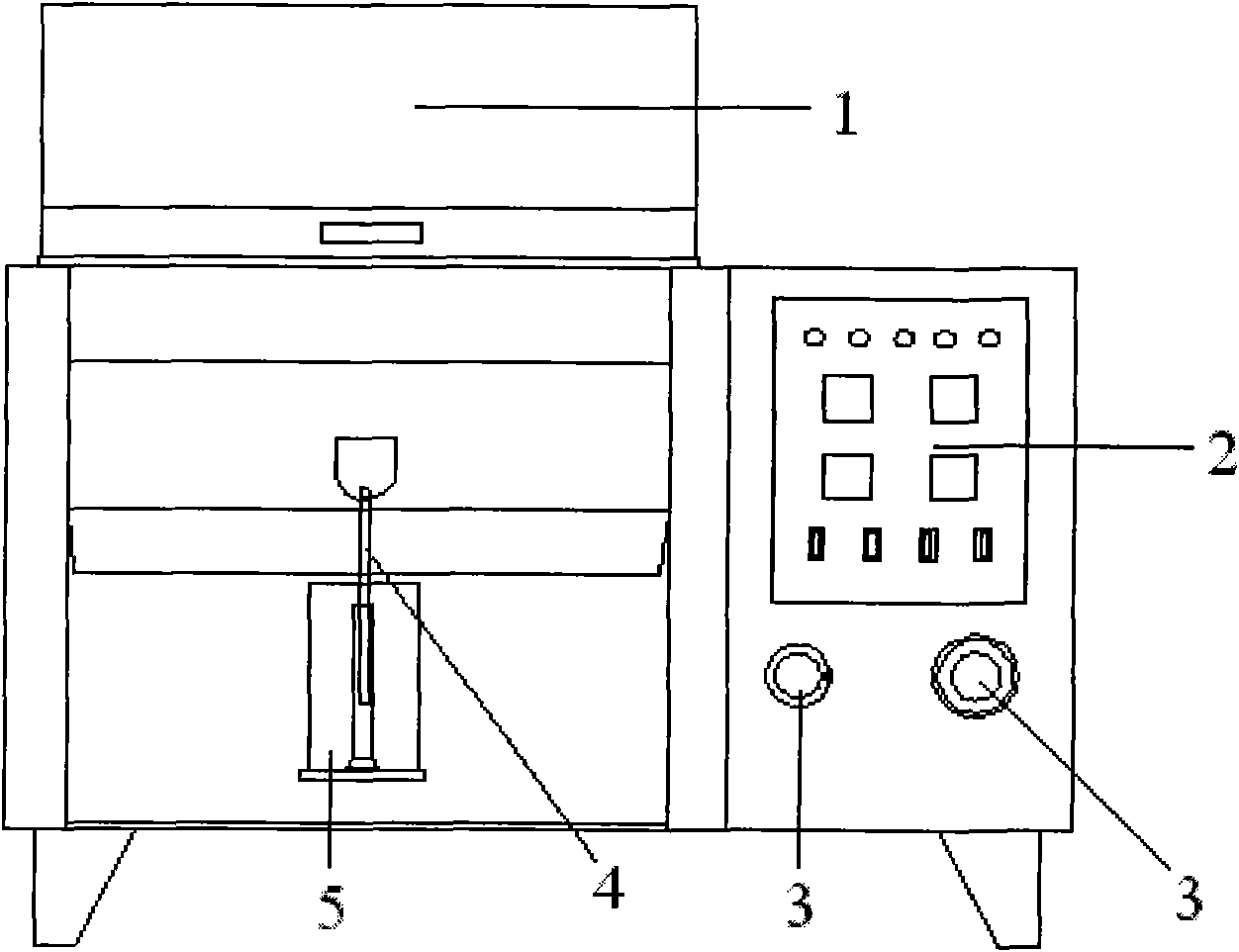
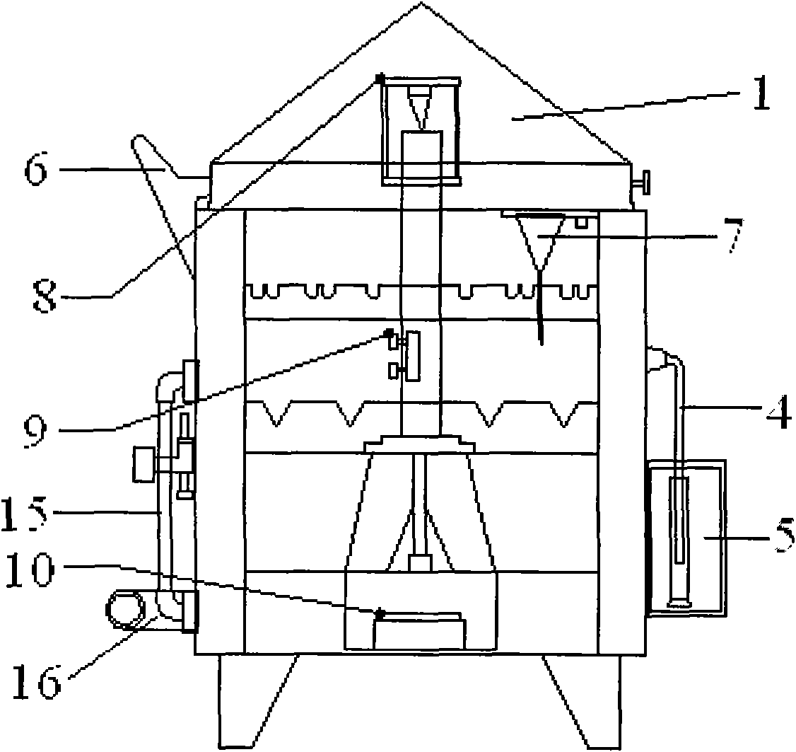
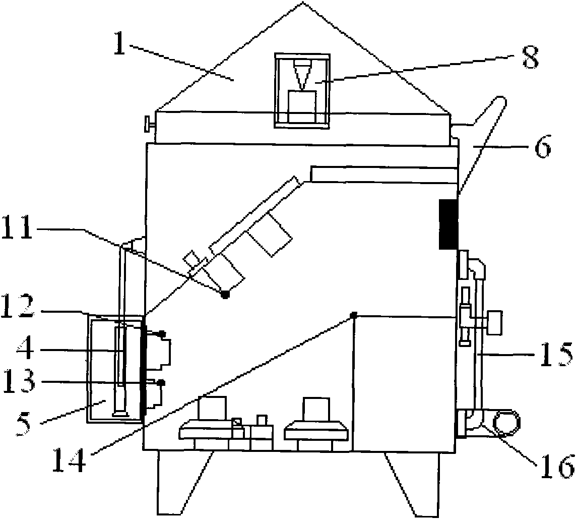
[0022] A salt spray corrosion test chamber, its front view is as follows figure 1 As shown, the internal structure diagram is shown in figure 2 As shown, the test chamber includes a control panel 2, a measuring cylinder 4, a heating pipe 10, a drainage pipe 15, a spray system and an electrical system. The body of the fog corrosion test chamber is made of polyvinyl chloride (PCV) imported from Germany. The top of the salt spray corrosion test chamber is provided with a transparent case cover 1, one side of the case cover 1 is provided with a support rod 6, the lower part of the case cover 1 is provided with a triangular funnel 7, the control panel 2 is provided on the right side of the front of the test chamber, and the measuring cylinder 4 is covered A measuring cylinder sheath 5 is arranged in the middle of the front of the test box, and a drain pipe 15 is arranged at the back of the test box and is connected with a saturated container 14 in the test box, and the saturated ...


PUM


Abstract

The invention relates to a salt mist corrosion test box. The test box comprises a heating pipe, a spray system, an electrical system, a control panel, a measuring cylinder and a drainage pipeline, wherein the heating pipe is arranged at the bottom of the test box; the spray system is arranged at the upper part of the test box; the electrical system is arranged on the side wall in the test box; the control panel is arranged on the right side of the front of the test box; the measuring cylinder is arranged at the middle part of the front of the test box; and the drainage pipeline is arranged on the back of the test box. Compared with the prior art, the test box which is made of polyvinyl chloride (PVC) reinforced hard plastic boards has finished surface, ageing resistance, corrosion resistance and shock resistance, is easy to clean and has no leakage; intermittent or continuous spray mode is used; and the test box performs laboratory simulation test on natural corrosion, copies an outdoor periodical environment, is simple for operation and has low expense.

Description

technical field [0001] The invention relates to a test device, in particular to a salt spray corrosion test chamber. Background technique [0002] The currently used salt spray corrosion test chamber has the following disadvantages: (1) The equipment in the salt spray corrosion test chamber is difficult to clean when the test is completed, and the inner box is prone to yellow spots and discoloration after the machine has been used for a period of time; And after a long time, the bottom of the box is easy to crack and it is not easy to repair. (2) Generally, the salt spray test takes a long time. During the test, it is impossible to see the change process of the sample in the box through the box cover during the test. At this time, the test box can only be stopped and then the box cover is opened. Continue to do the test again, which brings great perplexity and disadvantages to the test evaluation. (3) Only one of continuous spray or gap spray can be selected when the equip...

Claims


Application Information

Patent Timeline
Patent Type & Authority Applications(China)
IPC IPC(8): G01N17/00
Inventor 孙光林
Owner SHANGHAI LINPIN INSTR
Why Eureka
Try Eureka