
Lag angle control system in precise winding device

A technology of a winding device and a control system, which is applied in the field of lag angle control system, can solve the problems of high coil wiring precision, high labor intensity, and the wiring precision cannot meet the design requirements, etc., and achieves high winding precision and low labor intensity. Effect

Inactive Publication Date: 2011-05-11
THE NORTHWEST MACHINE
View PDF0 Cites 16 Cited by
  • Summary
  • Abstract
  • Description
  • Claims
  • Application Information

AI Technical Summary

Problems solved by technology

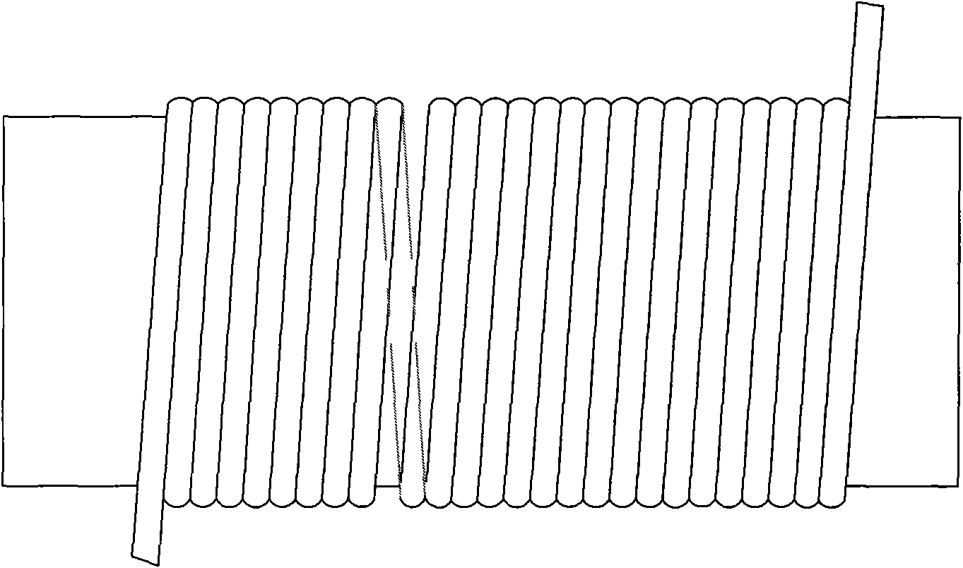
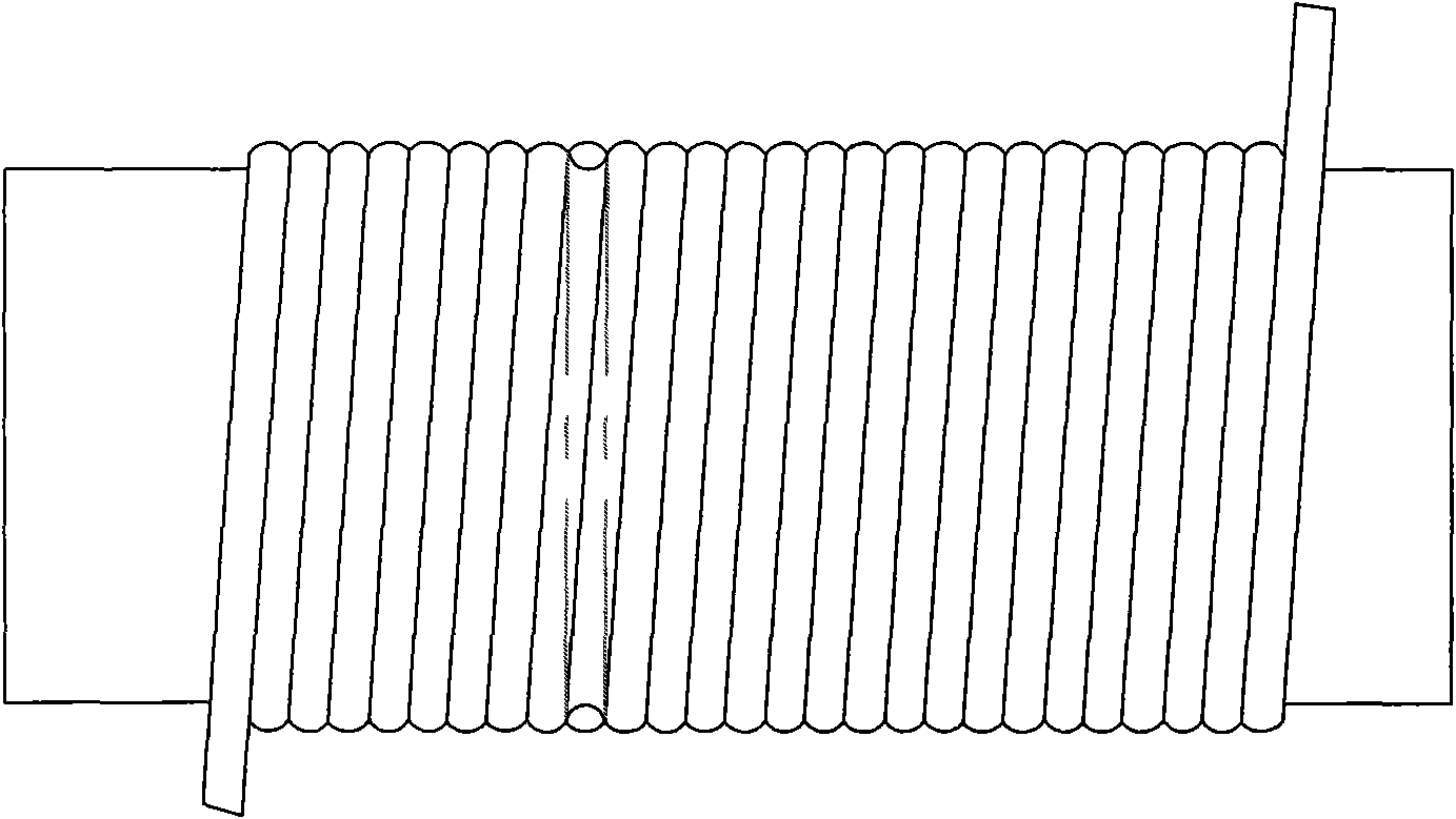
At present, high-precision AC servo systems and high-precision actuators are mainly used in the winding process of precision coils, which can fully meet the coil precision requirements in theory, but in practical applications, due to the change of wire diameter and wire tension Due to the influence of many uncertain factors such as the variation of the coil and the unevenness of the surface of the skeleton, some gaps and unevenness will appear on the surface of the coil, resulting in the accuracy of the wiring not meeting the design requirements.
Therefore, in some high-precision coil winding processes, the semi-automatic manual winding method is still used, which has low efficiency and high labor intensity. The most serious thing is that the accuracy of coil wiring is greatly affected by human factors, and the yield is low. , the quality is difficult to guarantee

Method used


Image

  • Lag angle control system in precise winding device
  • Lag angle control system in precise winding device
  • Lag angle control system in precise winding device

Examples


Embodiment Construction

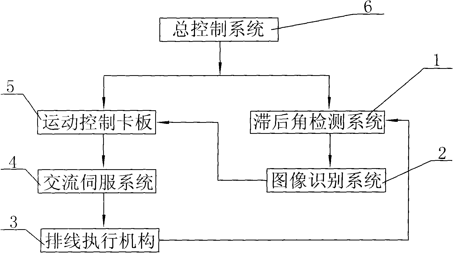
[0014] Such as figure 1 , a lag angle control system in a precision winding device of the present invention includes a precision camera device, a high-speed image processing system, and a precision cable arrangement system, wherein the precision camera device includes a lag angle detection system 1, and the high-speed image processing system Including an image recognition system 2, the precision cable system includes an AC servo system 4 and a cable actuator 3, and the cable actuator 3 is composed of a precision ball screw and a precision linear guide; the lag angle detection system 1 Connect the image recognition system 2 and the wiring actuator 3, and send the detection result to the image recognition system 2, which is then recognized by the image recognition system 2 and then controlled by the computer in the general control system 6. The wiring actuator 3 is connected to the AC servo system 4, and the precision ball screw is controlled by controlling the AC servo system 4...


PUM


Abstract

The invention relates to a lag angle control system in a precise winding device. The system comprises a precise camera shooting device, a high-speed image processing system and a precise wiring system, wherein the precise camera shooting device comprises a lag angle detection system; the high-speed image processing system comprises an image identification system; the precise wiring system comprises an alternating current servo system and a wiring execution mechanism, and the wiring execution mechanism consists of a precise ball screw and a precise linear guide rail; the lag angle detection system is connected with the image identification system and the wiring execution mechanism and used for sending a detection result to the image identification system, and after being identified by the image identification system, the detection result is controlled by a computer in a control system; the wiring execution mechanism is connected with the alternating current servo system and drives the precise ball screw to control the size of a wiring thread pitch through controlling the alternating current servo system; the alternating current servo system is also connected with a motion control card; and the motion control card is connected with the image identification system. The system has the advantages of high winding precision and small labor intensity and also realizes automatic control.

Description

technical field [0001] The invention belongs to the technical field of precision winding devices, and relates to a control system of a precision winding device, in particular to a lag angle control system used in a precision winding device of optical fibers and wires. Background technique [0002] The precision winding device is one of the key equipments in the production of precision electronic components. It is mainly used in the fields of electronics, electric power, aerospace, weapons and ships to manufacture precision electronic components such as potentiometers, resistors, sensors, and communication wiring coils. At present, high-precision AC servo systems and high-precision actuators are mainly used in the winding process of precision coils, which can fully meet the coil precision requirements in theory, but in practical applications, due to the change of wire diameter and wire tension Due to the influence of many uncertain factors such as the variation of the coil an...

Claims


Application Information

Patent Timeline
Patent Type & Authority Applications(China)
IPC IPC(8): G05D3/12B65H54/28
Inventor 邓鹤鸣
Owner THE NORTHWEST MACHINE
Learn More