
Packaging shell and packaging structure of edge type light emitting component

A technology of light-emitting components and packaging structures, applied in electrical components, laser devices, laser parts, etc., can solve the problems of light length, affecting light output efficiency, and easy loss.

Inactive Publication Date: 2011-05-11
ZHANJING TECH SHENZHEN +1
View PDF1 Cites 6 Cited by
  • Summary
  • Abstract
  • Description
  • Claims
  • Application Information

AI Technical Summary

Problems solved by technology

However, with such an arrangement, part of the light 14 emitted by the LED chip 12 needs to be reflected and diffracted by the side wall 11 before being emitted from the light-emitting surface 16 to the light receiver 18. Due to the long path of light, it is easy to lose and affect the light-emitting efficiency.

Method used


Image

  • Packaging shell and packaging structure of edge type light emitting component
  • Packaging shell and packaging structure of edge type light emitting component
  • Packaging shell and packaging structure of edge type light emitting component

Examples


Embodiment Construction

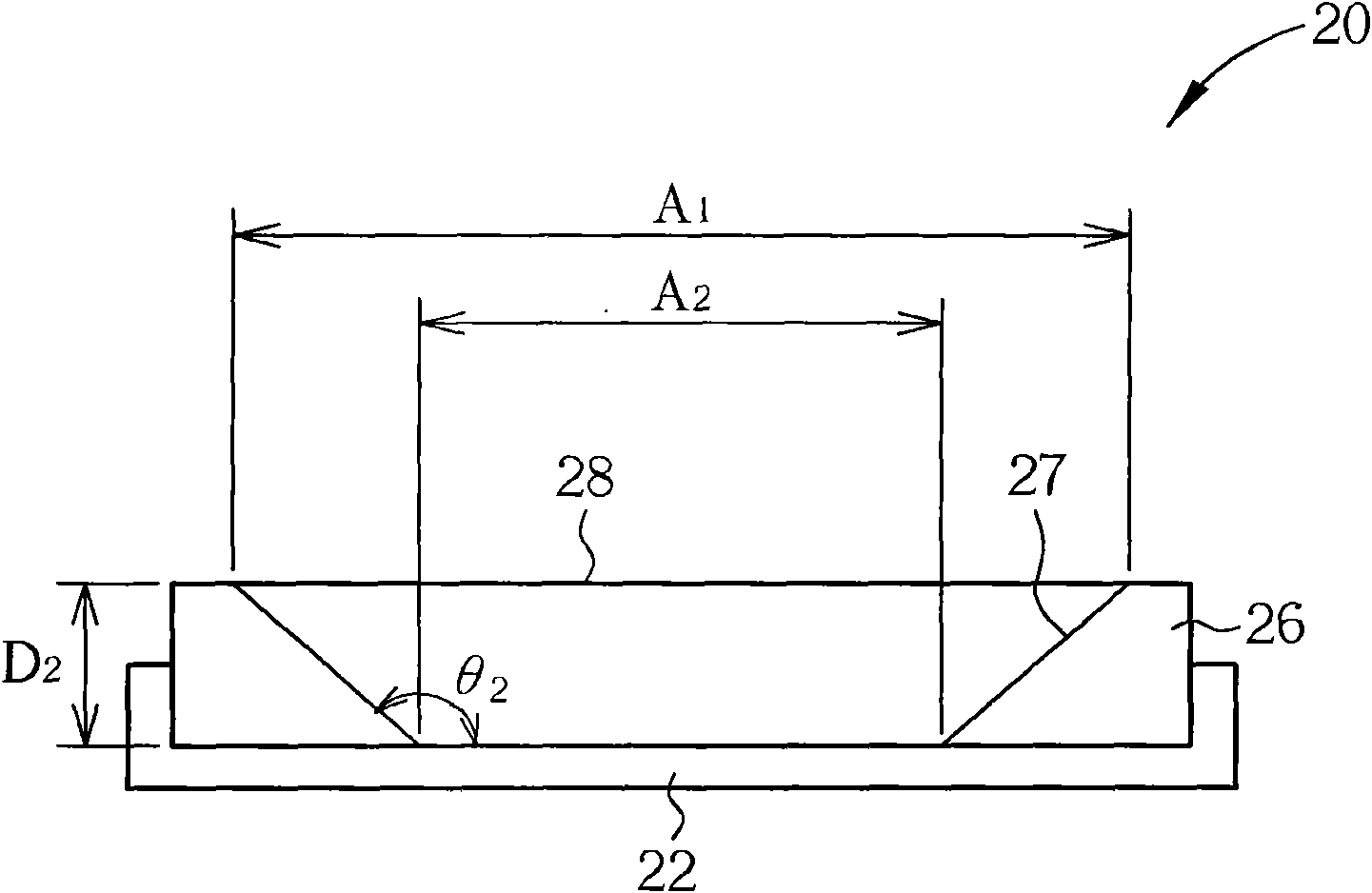
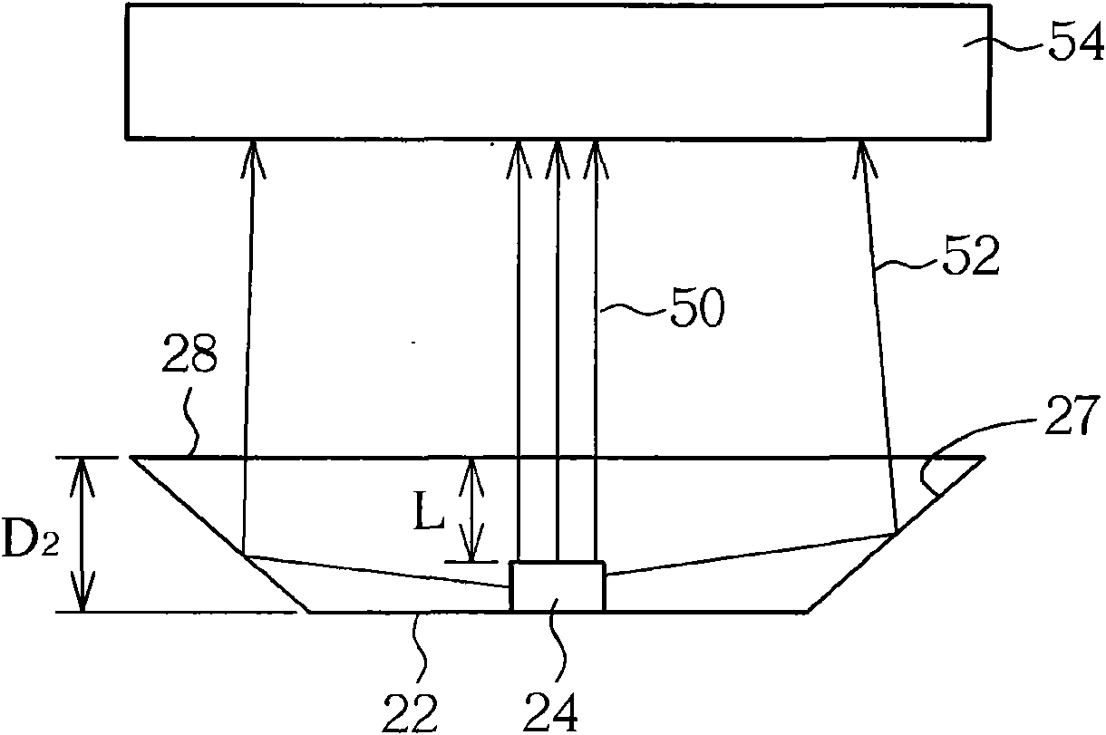
[0032] The light-emitting element of the side-light light-emitting element packaging structure of the present invention is located in a cup-shaped substrate, wherein the cup shell of the cup-shaped substrate is inclined outward so that the side wall and the base form an included angle of 140 to 150 degrees, and the cup shell has a The depth perpendicular to the base is 0.25mm to 0.3mm, and the mouth of the cup shell is a light-emitting surface, and the area of ​​the light-emitting surface is 1.5 to 2 times the area of ​​the base.

[0033] Such as figure 2 A schematic cross-sectional view of a specific embodiment is shown, and the package case 20 of an edge-lit light-emitting element includes the following: a base 22 . The base 22 can carry a light emitting element. The light emitting element can be, for example, a light emitting diode (LED), an organic light emitting diode, a resonant cavity light emitting diode, or a laser semiconductor chip. The cup shell 26 is combined w...


PUM


Abstract

The invention discloses a packaging structure of an edge type light emitting component, comprising a shell and a light emitting component, wherein the cup shell of the shell is inclined outwards so that the side wall and a base form an included angle of 140-150 DEG; the cup shell is provided with a depth vertical to the base, and the depth ranges from 0.25mm to 0.3mm; and the cup rim of the cup shell is an emergent surface of which the area is 1.5-2 times that of the base.

Description

technical field [0001] The present invention relates to a light emitting component packaging casing and packaging structure, in particular to a side-light type light emitting component packaging casing and packaging structure. Background technique [0002] Light emitting diodes (light emitting diodes; LEDs) have been used in lighting devices, such as flashlights, car headlights, light bulbs, and lamp tubes. In addition, they can also be used as backlights for devices, such as those used in TVs, monitors, and mobile phones. LCD backlight assembly (backlight module). The classification of backlight assemblies can be divided into direct type and edge type according to the light emitting direction of the LED chip on the substrate. Different types of products have their own requirements. [0003] The edge-lit LED backlight assembly in the prior art generally has a cup-shaped substrate on which the LED chip is placed, and the LED emits light. Some of the light is directly emitted...

Claims


Application Information

Patent Timeline
Patent Type & Authority Applications(China)
IPC IPC(8): H01L25/075H01L25/04H01L33/54H01L33/60H01L51/52H01S5/00H01S5/022H01S5/40
CPCH01L33/60H01L2224/48091H01L2224/48247H01L2924/00014F21S8/04F21V1/02F21V1/12F21V17/12F21W2121/00
Inventor 陈志明
Owner ZHANJING TECH SHENZHEN
Learn More