Delay interferometer using magneto-optic effect

A delay interferometer, optical path technology, applied in instruments, optics, light guides, etc., can solve problems such as slow response speed

Inactive Publication Date: 2011-05-11
FUJITSU OPTICAL COMPONENTS LTD
View PDF5 Cites 5 Cited by
  • Summary
  • Abstract
  • Description
  • Claims
  • Application Information

AI Technical Summary

Problems solved by technology

[0004] However, phase adjustment based on temperature control may have a slow response

Method used


Image

  • Delay interferometer using magneto-optic effect
  • Delay interferometer using magneto-optic effect
  • Delay interferometer using magneto-optic effect

Examples


no. 1 approach

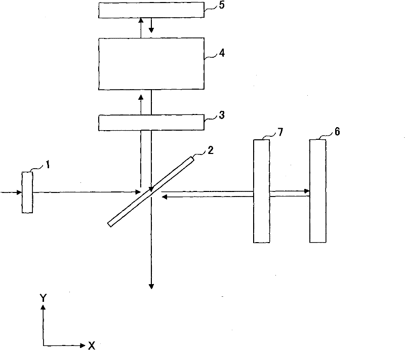
[0023] The delay interferometer disclosed here utilizes the magneto-optic effect for phase adjustment. Among various magneto-optical effects, Faraday rotation may be the most well-known and actually used effect. As an example of a device for phase adjustment, the delay interferometer disclosed herein employs a variable Faraday rotator (VFR).

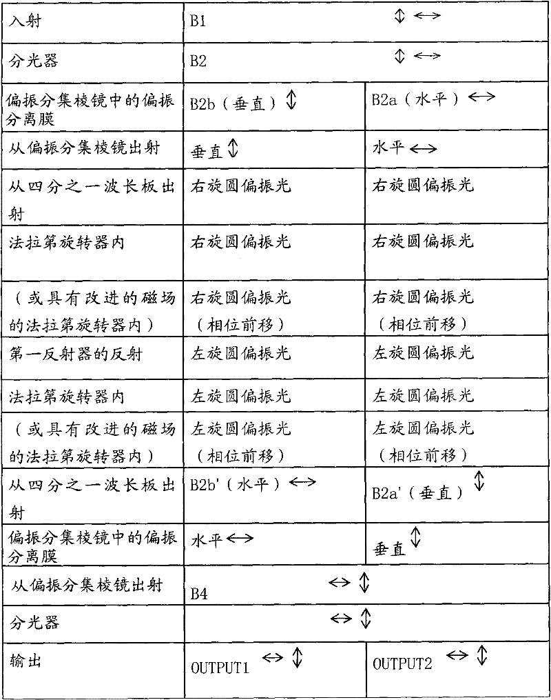
[0024] Faraday rotation is generally understood as the rotation of linearly polarized light. It should be noted, however, that Faraday rotation can also be defined as a physical phenomenon that occurs for circularly polarized light. Faraday rotation can provide a phase difference or optical path length difference between right-handed circularly polarized light and left-handed circularly polarized light.

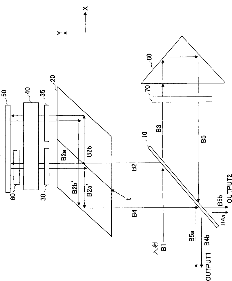
[0025] Faraday rotation produces a difference in optical path length for circularly polarized light, which is λθ / 2π when the wavelength is λ and the rotation angle is θ (expressed in radians). The optical path length can thus be adju...

no. 2 approach

[0070] A receiver according to a second embodiment will be described below. The receiver of the second embodiment utilizes the delay interferometer of the first embodiment. Before describing the structure of the receiver, the polarization dependent frequency shift (PDFS) will be described first.

[0071] PDFS refers to the phenomenon that the frequency (or wavelength) of the interfering light deviates due to the difference in optical path length between the interfering polarized beams. In a delay interferometer, there are many different factors that contribute to the difference in optical path length through polarization. It is preferable that this difference in optical path length due to polarization can be eliminated. In the delay interferometer described in the first embodiment, the two beams travel through the variable Faraday rotator such that these beams are susceptible to the magnetic field distribution in the variable Faraday rotator. Small differences in the Farada...


PUM


Abstract

A delay interferometer includes first and second optical paths into which incident signal light is split, a first converter including one or more conversion parts to convert the signal light on the first optical path into circularly polarized light and to convert the circularly polarized light into linearly polarized signal light, a phase adjuster to shift an optical phase of the circularly polarized light through a magneto-optic effect, and a second converter to convert a polarization state of the signal light on the second optical path into substantially the same polarization state as a polarization state of the linearly polarized signal light.

Description

technical field [0001] Embodiments of the invention relate to delay interferometers, receivers and methods of producing delay interferometers. Background technique [0002] As technologies capable of realizing high bit rate optical transmission in the range of 40G / s per wavelength or higher, such as differential binary phase shift keying (DPSK) modulation, differential quadrature phase shift keying ( Optical modulation schemes such as differential quadrature phase shift keying (DQPSK) modulation have attracted people's attention. Receivers used in phase modulation schemes such as DPSK and DQPSK employ delay interferometers to detect phase information. [0003] The delay interferometer uses two beams to interfere with each other, and the phase difference between the two beams can be stabilized within the range of 1 / 100 of the wavelength. Typically, temperature-based control is used to adjust the phase difference. For example, phase compensators made of materials with therm...

Claims


Application Information

Patent Timeline
IPC IPC(8): H04B10/12H04L27/22G02F1/09H04B10/516H04B10/548H04B10/61
CPCG02B6/29352G02F1/09G02F1/092G02F2203/20G02F2203/21G02F2203/50G02F1/212G02F1/215
Inventor 福岛畅洋
Owner FUJITSU OPTICAL COMPONENTS LTD
Why Eureka
Try Eureka